Curve
![]()
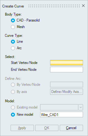
Dialog Box
This is used to create linear or arc edge using nodes or vertices. It will create new wire body for each edge. This edge can later be meshed to create number of bar elements. Element size is determined by specifying the mesh size or number of elements. Turn ON the equivalence toggle makes the wire body corner nodes equivalenced with the start and end node.
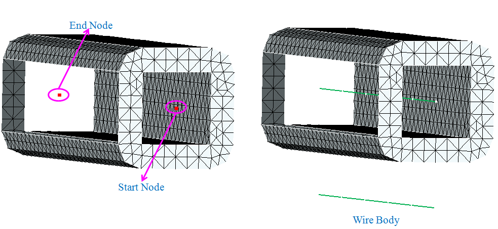
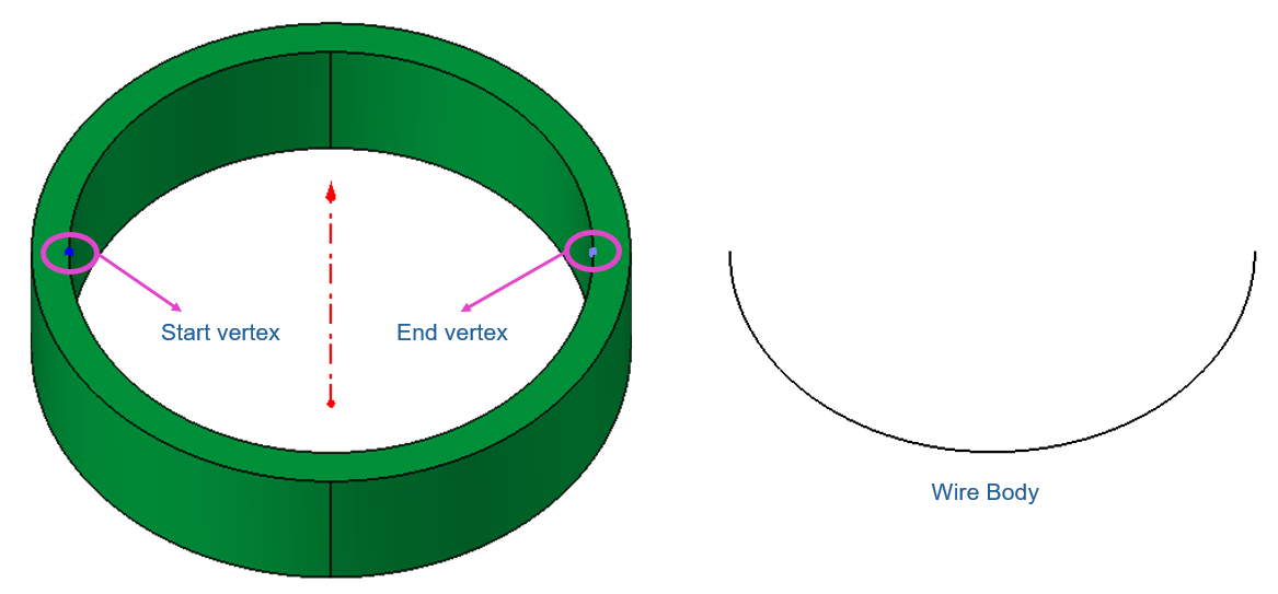
Linear
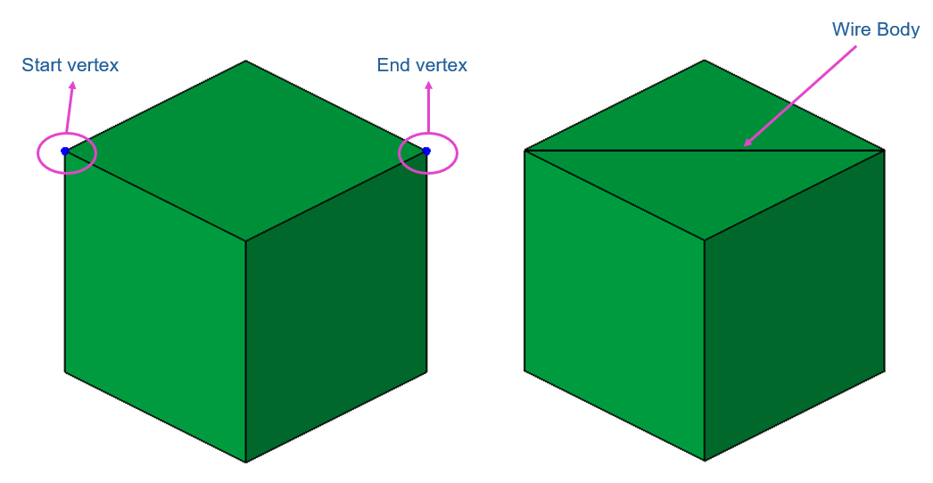
Selecting the start and end node or vertex will create linear edge between those two nodes.
Example
Select the start node and end node. Specify the number of elements as 5 and turn ON equivalence option. This will create new wire body with specified number of elements and corner nodes get equivalenced.
CAD - Parasolid
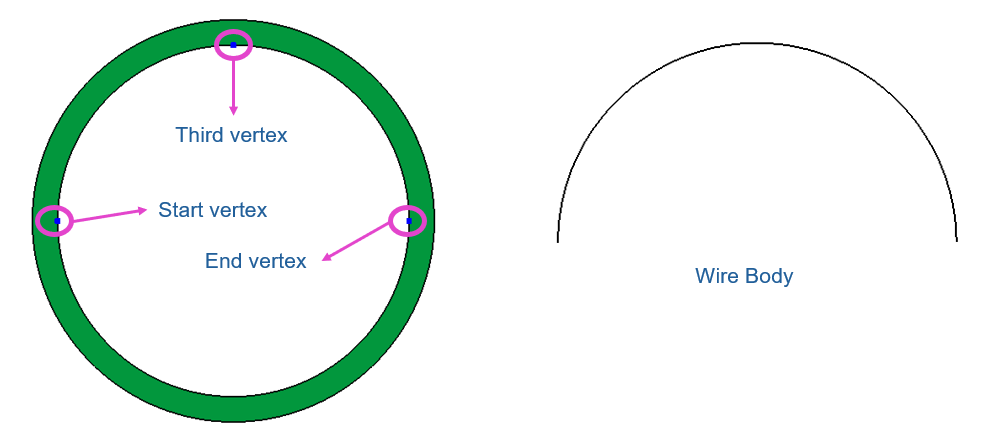
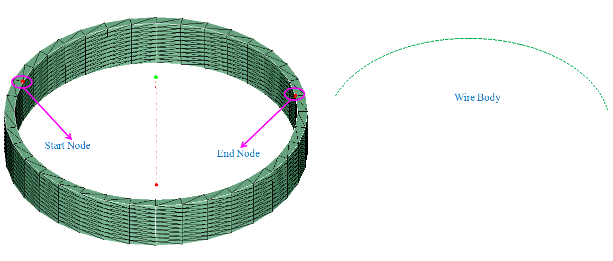
Arc
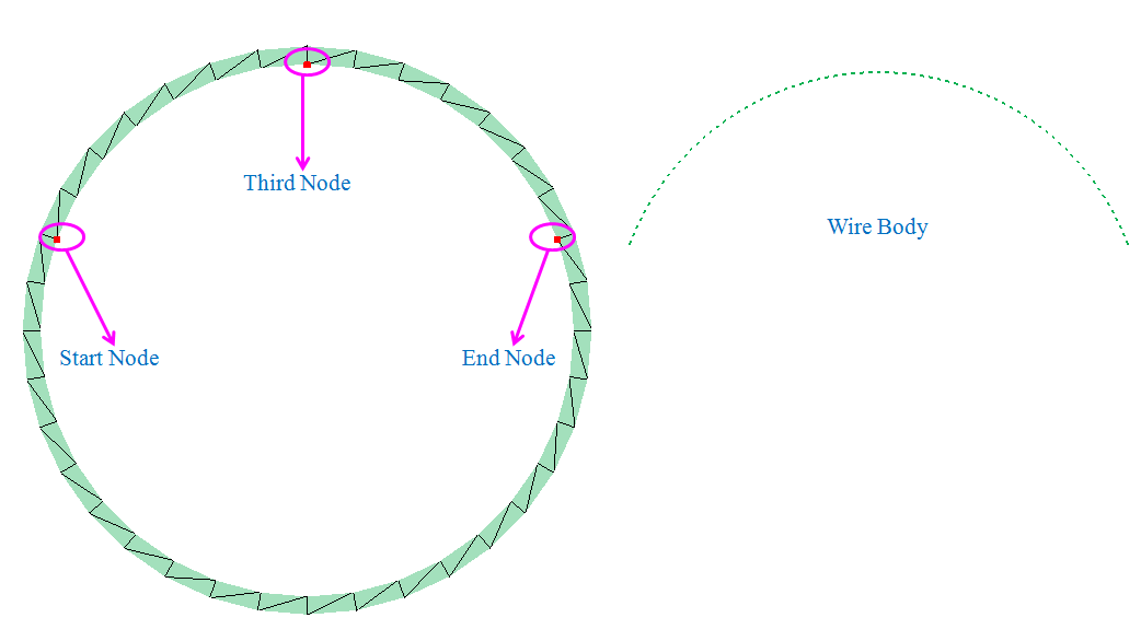
This option is used to create a circular edge between the nodes or vertices. Circluar edge can be created by specifying the circular axis or by specifying the third node or vertex. "Define Axis" will create an edge that passes through axis. Axis will calculate the radius of the arc. "By Vertex/Node" will create an edge that passes through third node or vertex. Selected third node or vertex define the radius of the arc.
Select the start node and end node. Define the axis and specify the number of elements and turn ON the equivalance option. This will create the circular edge that passes through the defined axis.
CAD - Parasolid
Select the start node and end node. Choose by node option and specify the third node. Selected third node define the radius of the arc. Specify the number of elements. This will create the circular edge that passes through the third node.
CAD - Parasolid