Chain
![]()
Introduction
This operation is useful in identifying a set of element edges, referred to as a chain, that forms a closed loop. There are three options Angle, Plane and Nodes.
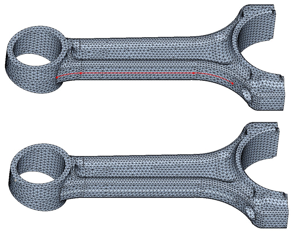
The angle option takes an element edge as a starting point and collects adjacent element edges to form a topological edge. In case the topological edge forms a closed loop, a face, bounded by this topological edge can be created. From the start element edge, the adjacent element edges are collected. For each of the end nodes, the edge that forms the maximum angle is identified. These edges are collected with the start edge to form a chain. At the 2 end nodes of the chain, edges that form the maximum angle are identified and added to the chain. This continues until the two end of the chain meets or one of the limiting conditions are met. The limiting condition can be the maximum angle or the boundary of a face.
The Plane option defines a plane that identifies all boundary and internal nodes that are close to this plane. A tolerance is provided to include nodes that are close to the plane. An edge on the boundary or an internal face can be created.
The Node option identifies the element edges along the path defined by the nodes and creates topological edge on it.
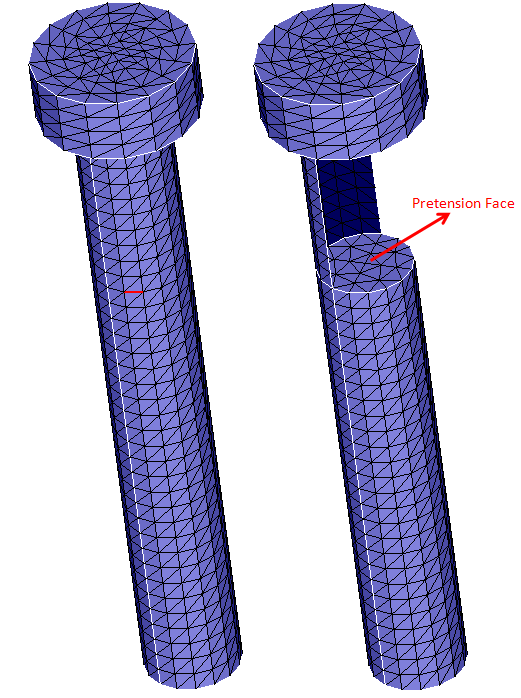
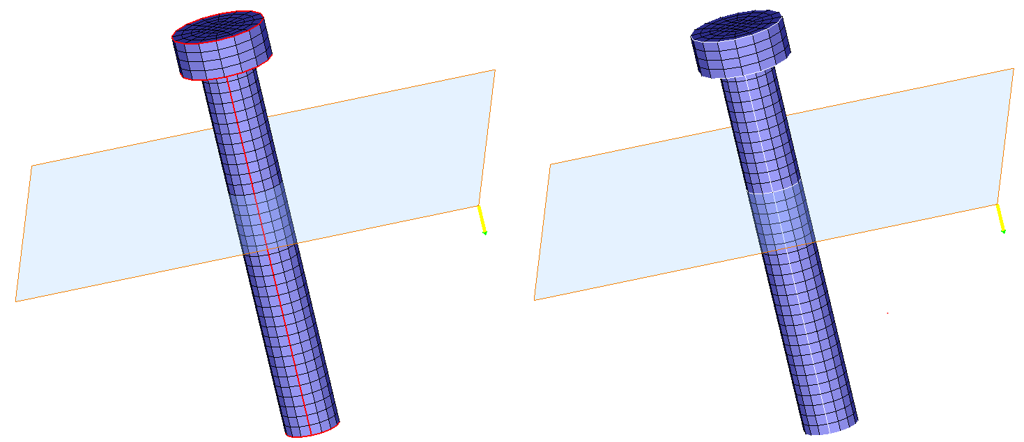
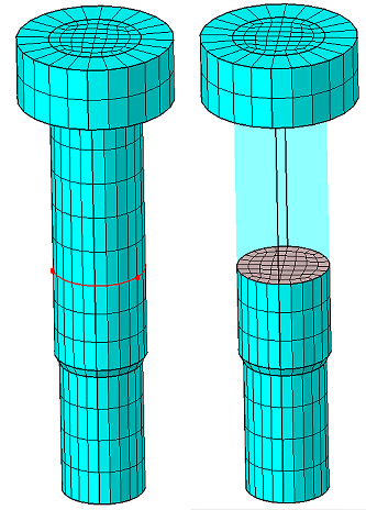
Chaining operation is useful for introducing a pretension surface for a bolt or for breaking a face into smaller portions to apply constraints or load. Bolt pretension surfaces are not present in a CAD model. On a bolt mesh, can be a tet-mesh or hex-mesh, a set if element faces that break the bolt into 2 parts are required to assign bolt pre-tension load. This can be created by selecting an element edge on the bolt surface mesh, along the circumference, and calling the chain function with the "Create Face" option.
This function is useful to collect element edges along a path of a surface mesh with an iso-mesh pattern.
Angle
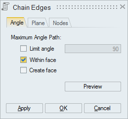
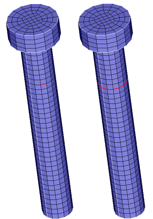
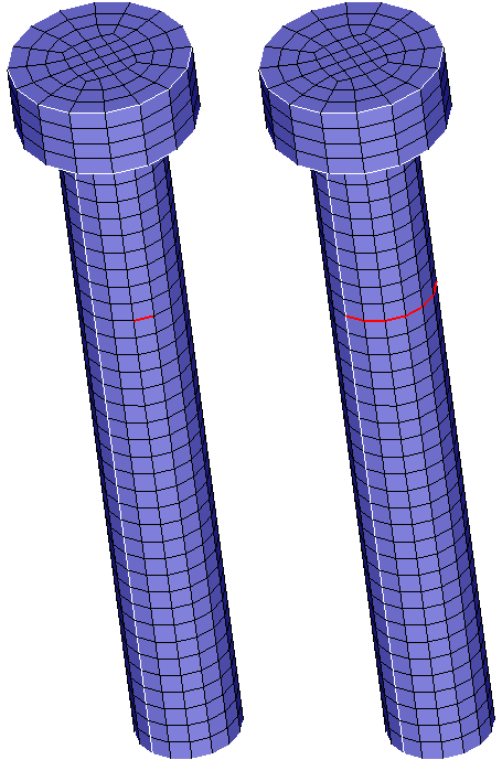
- Select an Element Edge. Adjacent element edge that makes the maximum angle at the end nodes will get added to the chain. This is repeated for each free nodes of the chain.
- The chain can be stopped by specifying the Limit Angle. The angle between the
adjacent element edges in the chaining should be between Limit Angle and 180
degrees. If the angle of all adjacent the edges are less than the Limit Angle,
then the chaining stops.
- "Within Face" option collects the adjacent element edges from the face of the
input element edge alone.
- If "Create Face" option is enabled, then an internal face will be created
in addition to topological edges on the boundary. This works for surface
tri-mesh body . If the body were a surface tri-mesh, then an internal face will
be created. Surface mesh body with Quad elements is not supported.
"Preview" option can be used to see the edges that form the chain before the edge is created.
Plane
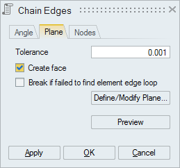
- It will create a topological edge for the found element edge chain on the
defined planes for the selected faces/bodies.
An internal face gets created using these topological edges if the "Create Face" toggle is ON. In the case of solid bodies, the face creation only happens if any 3D element face lies on the defined plane.
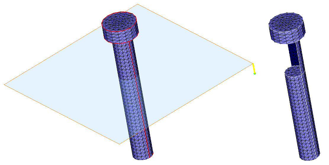
Using Single Plane:
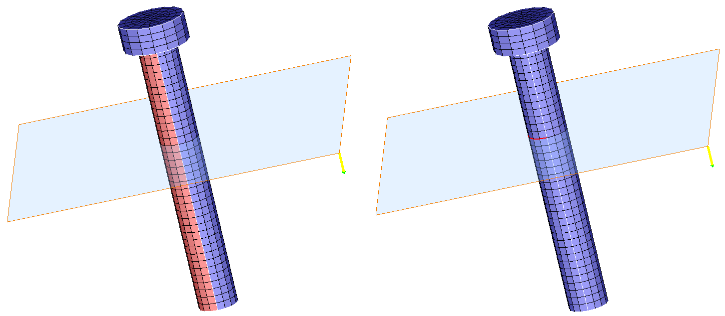
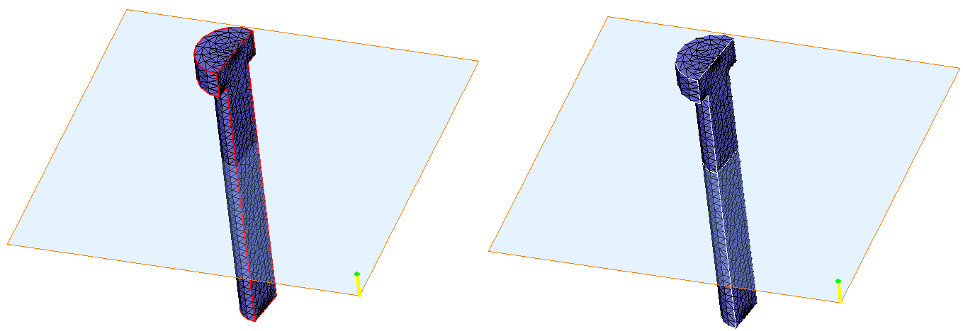
Using Multiple Planes:
Input
Output
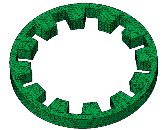
- If the "Create Face" option is enabled, then it will create an internal
face.
 Note:
Note:- The "Create Face" option will only work for the surface body with tri-elements or a volume body.
- The "Create Face" option is supported only for single-plane definition.
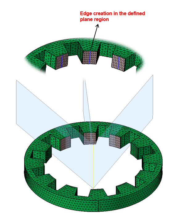
- If suppose nearest element edge loop is not able to find from the defined plane
then turn on the "Break if failed to find the element edge loop" option. This
will create the chain in the defined plane region.
- "Preview" option is used to display the chain. The user can then decide to create or discard the chain.
Nodes
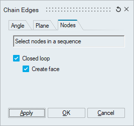
- This option is used to identify the elements edges along the path defined by the nodes and create topological edges using the same.
- If closed loop option is ON, it creates an edge between first and last node to
form a closed loop.
- If “Create face” toggle is ON, then an internal face will be created
using the edges created by element edges.Note: "Create face" option will only work for surface mesh body with tri-elements or a volume mesh body with hex/wedge elements.
- If “Create face” toggle is ON, then an internal face will be created
using the edges created by element edges.