Edge offset
![]()
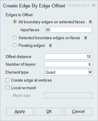
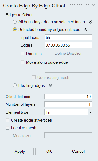
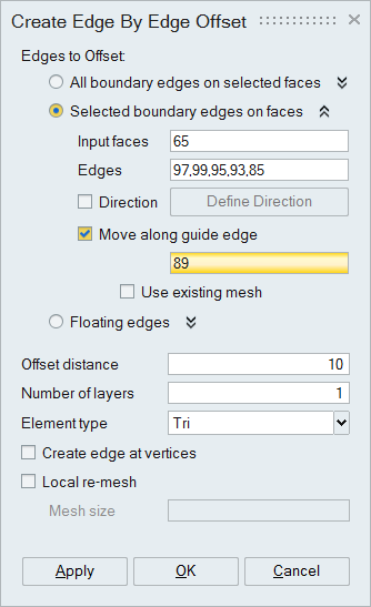
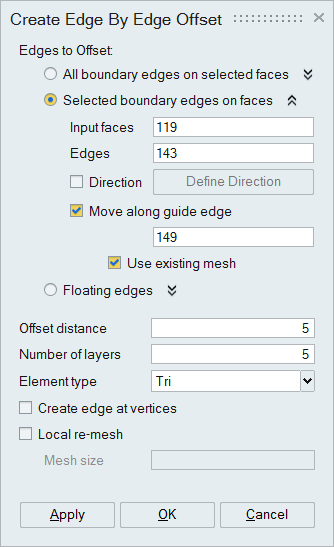
Dialog Box
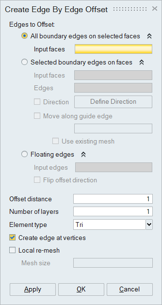
The Edge Offset tool is used to create edges inside a face by offsetting the boundary edges. Some or all of the boundary edges can be selected for offset.
The offset is performed on mesh bodies and modifies the existing surface mesh.
- Edge to Offset
- All boundary edges on selected faces
In this case all the edges of the selected face are offset.
- Selected boundary edges on face
In this case user can choose the edges on the boundary of the selected face to be offset. The selected edge id's will be displayed in the edit box.
- Direction: Defines the direction in which the edges will be offset. By default the edges will be offset along the normal direction.
- Move along guide edge: When we do the edge offset, the node connected to the guide edge will be offset along the guide edge.
- Use existing mesh: By activate this checkbox, you use the existing nodes in the guide edge for offset for the number of layers specified.
- Floating edges
In this case user can select floating edges to offset from a face.
Offset direction is displayed as soon as a floating edge is selected. User can change the direction using Flip offset direction option.
- All boundary edges on selected faces
- Offset distance
This represents the distance by which an edge will be offset.
- Number of layers
This represents the number of layers to be created in the offset surface.
- Element type
This represents the type of elements to be created in the offset surface.
- Create edge at vertices
By activating this checkbox, you can create an edge between the vertices between selected edges and the newly created internal edge.
- Local Re-Mesh
Activating this checkbox, will remesh selected surfaces after offsetting elements by using the given Mesh size.
Example 1
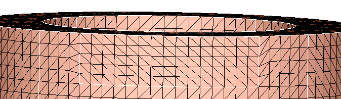
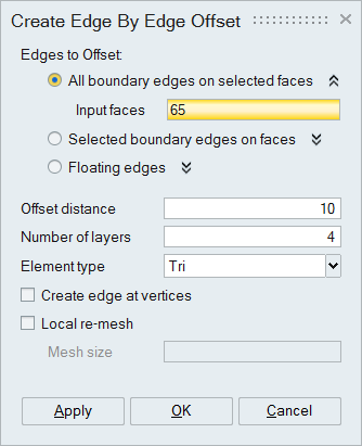
Select a face and specify an offset distance of 10. Since offset all edges on the selected faces option is selected, all the edges are offset as shown.
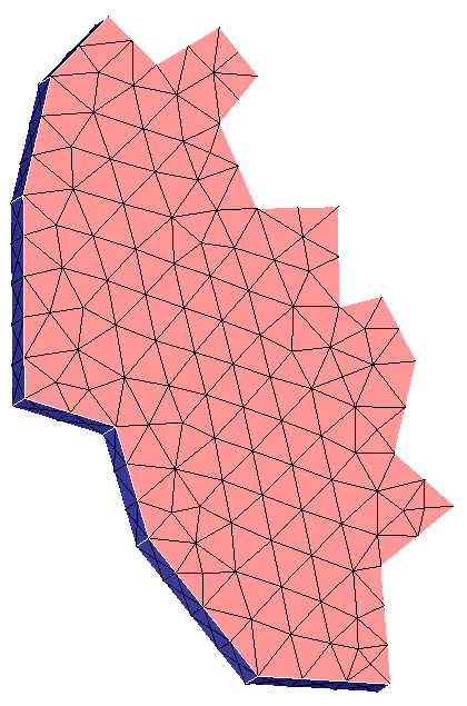
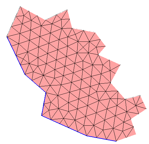
The face is broken in to 2 faces.
Example 2
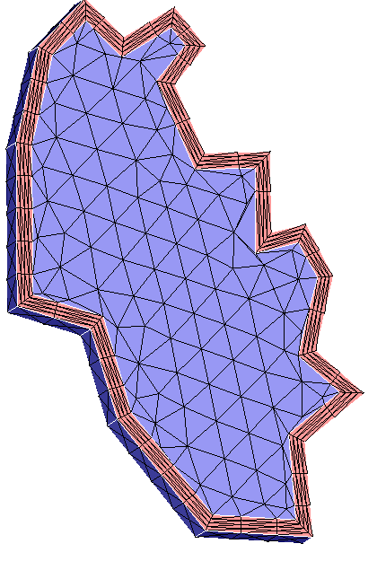
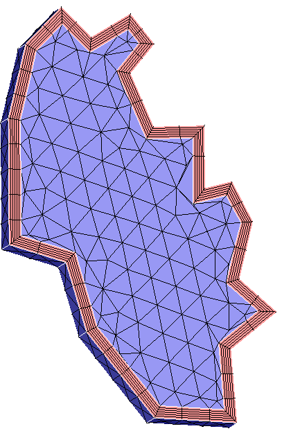
Select a face a and enable the offset all edges on selected faces. Choose the Quad layer option and specify the No. of layers as 6 and click ok. All the edges are offset as shown.
All the edges from the selected face are offset to the specified offset distance and the specified Quad layer will be created.
Example 3
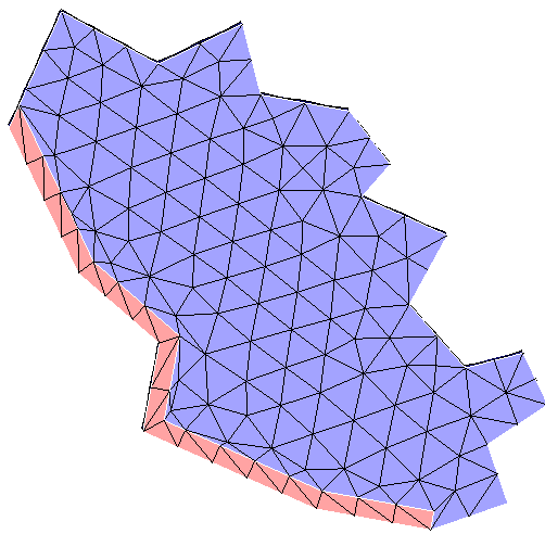
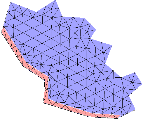
Select a face and enable the offset selected edges on faces option and selected some of the edges on the face. Choose Tri layer option and click ok. The selected edge is offset as shown.
All the edges from the selected face are offset to the specified offset distance and the specified Quad layer will be created.
Example 4
Select a face and enable the offset selected edges on faces option and selected some of the edges on the face. Specify the direction to offset.
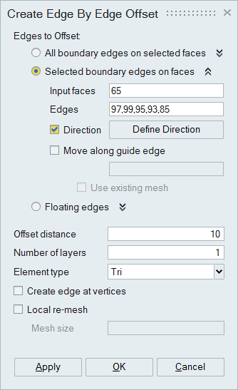
The selected edges are offset in the specified direction and the face is broken in to 2 parts.
Example 5
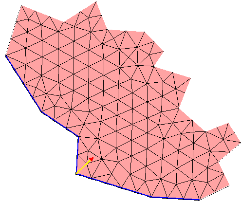
Select a face and enable the offset selected edges on faces option and selected some of the edges on the face. Select the move along guide edges and select the edge shown in the picture.
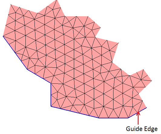
The selected edges are offset and the face is broken in to 2 parts. In this example we can see the node connected to the guide edge is moved along the guide edge instead of normal direction. Check the example 3 output to see the difference.
Example 6
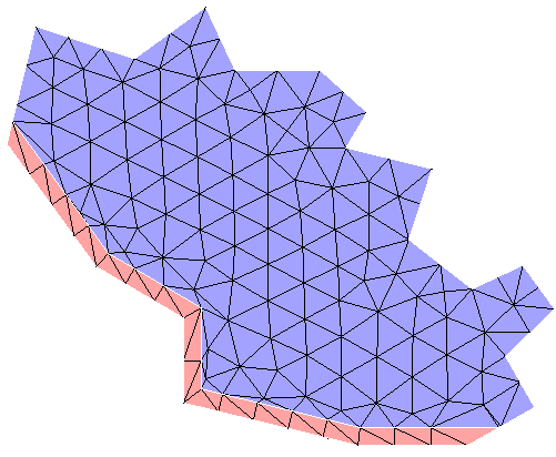
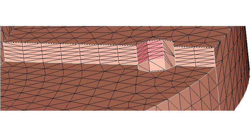
Select a face and enable the offset selected edges on faces option and selected some of the edges on the face. Select the move along guide edges and select the edge shown in the picture. Select the use existing mesh option with one layer of Tri element.
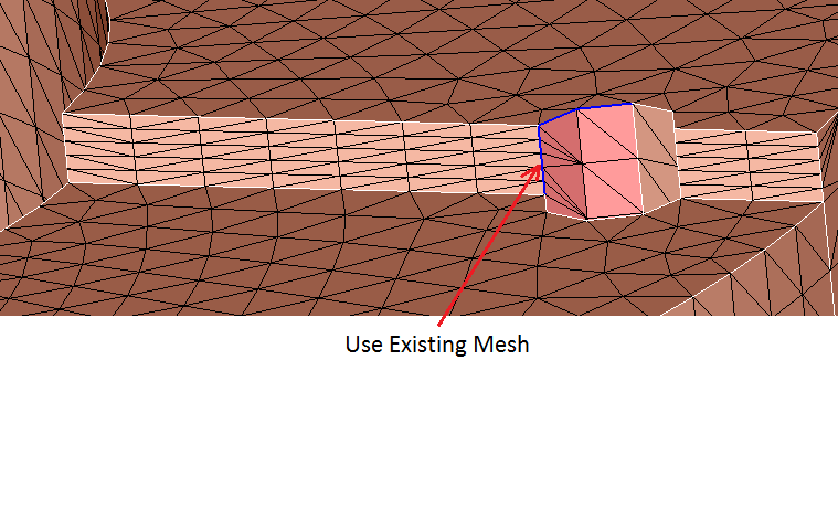
The selected edges are offset along the guide edges and the face is broken in to 2 parts. In this example we can see the existing nodes in the guide edges are used to offset.
Example 7
Select a face and enable offset all edges on selected faces and select the create edge at vertices. Select the Quad layer and specify the No. of Quad layer as 3 and click ok.

All edges from the face are offset and the specified Quad layer is created and edges will be created at the vertices.
Example 8
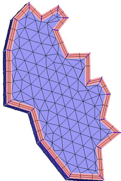
Select a floating edge. Specify the offset distance as 20, Number of layers as 5, select Tri element type and click OK.
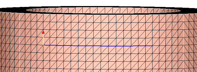
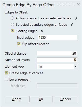
Given floating edge is offset to a distance of 20. It has created a tri surface with 5 layers.