Sets
![]()
1. Create Sets
- Node sets
- Shell element sets
- Solid element sets
- Surface element sets
- Rigid Body Element (RBE) sets
- Membrane element sets
- Degrees of Freedom (ASET)
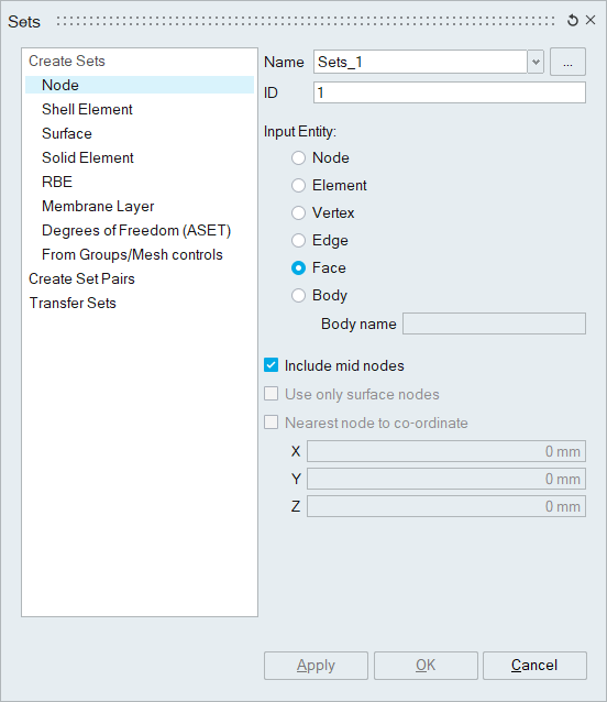
Set ID can be defined for Optistruct, Nastran, Permas and RADIOSS.
- Node sets can be created by selecting either face /
edge / vertex / node / element / body.
- Include mid node option can be used to include or skip the mid nodes in the selected entity.
- Use only surface nodes is used to create node set, with the nodes that are attached to the faces of the body.
- The Nearest node to coordinate option creates a node set by finding the nearest node to the specified coordinate (XYZ position) from the selected body.
- Shell element sets can be created by selecting either
face / element / body. The elements will follow the assigned ID range of the
associated body / sub-model in the assembly browser.
- The Create Linear shell element layer creates a linear shell element layer with equivalenced nodes over the selected bodies. This is useful to create a layer of shell elements over the faces of the higher order volume meshed bodies.
- Surface sets can be created by selecting either face / element / body. This option is used to create solid element surface set.
- Solid Element sets can be created by selecting either
face / element / body / region. This option is used group solid elements.
- User can select already created sets along with the body input to
create solid element set for Abaqus.
- Input sets can be,
- Membrane sets
- Shell element sets and
- Solid element sets.
- Input sets can be,
- The include only surface solid elements creates solid element set with solid elements that are attached to faces of the solid body. By default, all the elements of the selected solid body will be included in solid element set.
- The include solid element attached to face option creates solid element set with solid elements that are attached to the face elements of the selected face.
- The include solid element attached to face nodes option creates solid element set with solid elements that are attached to the nodes of the selected face based on number of layers specified.
- User can select already created sets along with the body input to
create solid element set for Abaqus.
- RBE sets can be created by selecting either Rigid Body Elements (RBE Elements) / Rigid Body Element bodies (RBE Bodies).
- Membrane Element sets can be created only from volume
meshed bodies (for Abaqus only). Either face / element / body can be given
as input. The membrane elements will follow the assigned ID range of the
associated body / sub-model in the assembly browser.
- The Create Linear Membrane element layer creates a linear membrane element layer with equivalenced nodes over the selected bodies. This is useful to create a layer of shell elements over the faces of the higher order volume meshed bodies.
- The Create Linear Membrane elements connecting mid nodes creates a linear membrane element layer by connecting the mid nodes of the tetrahedral face with 4 tri elements.
- The Reduced integration quad elements option used to specify the quad elements present in the membrane set as reduced integration elements (Ex: M3D4R). It is supported only for Abaqus solutions.
- Degrees of Freedom is used to define boundary / main
degrees of freedom to use as a external degrees of freedom on the
substructure or super element assembly. Either face / edge / vertex / node /
element / body can be given as input.
Cards supported by Degrees of Freedom set for various solvers
Solver Supported Cards OptiStruct ASET/ASET1 Nastran ASET/ASET1 Abaqus *Retained Nodal DOFs Ansys M - From Groups/Mesh controls is used to create sets
automatically using entities in predefined Local Mesh Controls /
Groups.
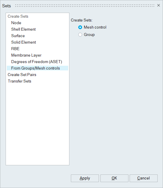
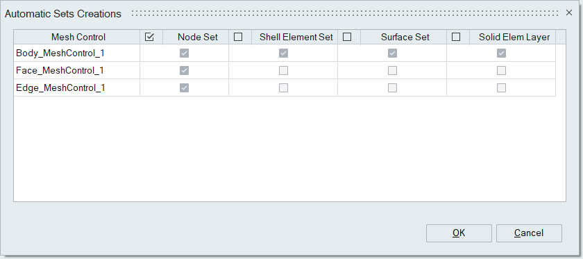
- The Mesh Control option is used to create
sets from predefined local mesh controls. When this toggle is
checked, Automatic Sets Creation dialog box
will appear. This dialog lists the mesh controls for which sets can
be created.
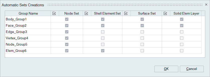
- The Group option is used to create sets from
predefined groups. When this toggle is checked, Automatic
Sets Creation dialog box will appear. This dialog
lists all the groups for which sets can be created.
- The Mesh Control option is used to create
sets from predefined local mesh controls. When this toggle is
checked, Automatic Sets Creation dialog box
will appear. This dialog lists the mesh controls for which sets can
be created.
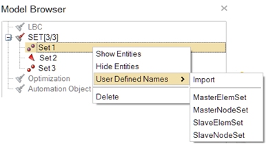
Set Name: Predefined set names can be imported and assigned to sets. The Surface names from contact definition file (*.dat or *.prp) can be imported and these names can be used for assigning set names.
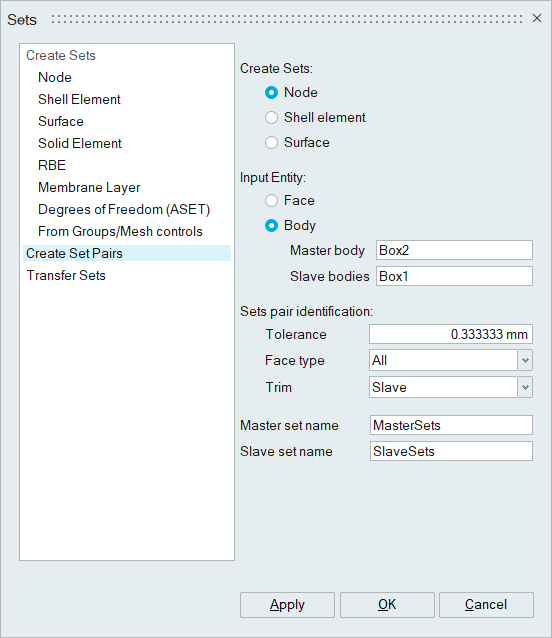
2. Create Set Pairs
This option is used to create node / shell element / solid element sets for creating contact pairs. Contact pairs between the given main and secondary bodies within the specified tolerance are found out and sets are created. Sets faces will be trimmed based on trim option and define the name for both main and secondary sets.
3. Transfer Sets
This option is used to transfer sets from source to destination body based on CAD ID (or) Persistent ID. Sets can be transferred (moved) or copied to Destination Body. One use of this tool is when sets are defined on a CAD model and they have to be transferred over to the mesh body derived from this CAD body.
![]()