Mapping
![]()
This tool used to map the Load/Results data from one mesh to another mesh.
Description
- Data Table
- Data Table + Model
- Results Data + Model
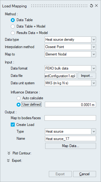
1. Data Table
This method of mapping is used to map a load/results data available in X,Y,Z,Load/Results Value format on to a mesh.
- Data type:
Option used to select the type of load to be mapped. This determines the number of data that needs to be mapped.
Pressure,Temperature,Heat source density and Flux - Only magnitude data will be mapped.
Convection - Temperature and Heat Transfer Coefficient data will be mapped.
Force and Enforced Displacement - Force (Fxyz & Mxyz)/ Displacement (Uxyz & Rxyz) will be mapped.
User Defined - Multiple data will be mapped.- This option can be used to map multiple user data from a reference to a required mesh in a single mapping process.
- First row of the input must have labels (E.g. X, Y, Z, Force, Temperature, Heat Loss,,, HTC).
- User need to give input in Format: X, Y, Z, Data1, Data2, Data3,,, DataN.
- User can plot to verify the mapped values and export the mapped values.
AcuSolve initial condition - Multiple boundary conditions can be mapped.- This option is used to map the results from oil sloshing simulation (solved by nanoFluidX solver) as initial conditions for the CFD problem (primarily for AcuSolve).
- User need to give input in Format: X, Y, Z, Vel-X, Vel-Y, Vel-Z, pressure, species proportion coefficient. This format can be exported from nFX.
- Interpolation method:
Option used to select the mapping algorithm.
- Closest Point: This method of mapping identifies the closest point from the input data for each node of the mesh and performs the mapping.
- Weighted Distance: This method of mapping identifies set of points from the input data for each node of the mesh. With the identified set of points, the mapping will be done by assigning weightage to each of the points based on the distance from the node.
- Quad Interpolation: This method of mapping creates virtual quad elements for the selected surface and does the mapping based on Shape function interpolation. This method is applicable only for pressure mapping.
- Force Balance: This method distribute the forces in the reference points to the mesh without altering the force balance equilibrium. This method is applicable only for data type - force.
- Map to:
Option to select the reference (Element Node/ Element Centroid) considered for mapping.
For surface based loads, its better to use Element centroid approach.
For node based loads, Element Nodal is a better approach.
- Data format:
Option to import the reference data from a text file. The reference data has to be of the format X,Y,Z,Load Value.
For the Heat source density, Flux - input format from FEKO is supported
- Data file:
For mapping the transient data (Temperature / Pressure), User can select multiple files. Each file represent data at a particular time step.
- Data unit system:
Option added to read the data from input file based on the unit system specified. This helps to map and visualize the output in user desired system.
- Influence distance:
Option used to specify the search limit - This is the tolerance within which the input data for each node will be considered for mapping.
Auto Calculate will determine the search limit based on the average element size.
- Map to bodies/faces:
Option to select the body/face to which the reference data needs to be mapped.
For node based loads, select body for mapping whereas for surface based loads, select faces.
- Create Load:
Option to create loads automatically with the output data of the mapping.
Data type Load Pressure,Temperature,Flux Pressure/Temperature/Flux Convection Convection Enforced Displacement Enforced Displacement Force Force Heat source density Heat source density AcuSolve initial conditon Initial condition - velocity, pressure, species
2. Data Table + Model
This method of mapping is used to map a load/results data with its corresponding mesh on to a new mesh.
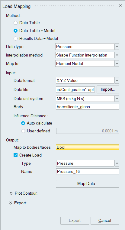
- Data type:
Option used to select the type of load to be mapped. This determines the number of data that needs to be mapped.
Pressure,Temperature, Heat Source Density and Flux - Only magnitude data will be mapped.
Convection - Temperature and Heat Transfer Coefficient data will be mapped.
Force and Enforced Displacement - Force (Fxyz & Mxyz)/ Displacement (Uxyz & Rxyz) will be mapped.
User Defined - Multiple data will be mapped.
- Interpolation method:
Option used to select the mapping algorithm.
Shape Function Interpolation: The mapping is done based on Element Shape function parameters.
- Map to:
Option to select the reference (Element Node/ Element Centroid) considered for mapping.
For surface based loads, its better to use Element centroid approach.
For node based loads, Element Nodal is a better approach.
- Data format:
Option to import the reference data from a text file. The reference data can be any one of the below format
- X,Y,Z,Load Value
- Node Id, Load Value
- Element Id, Load Value
- Nastran Bulk Data exported from Altair FLUX software and EPL file exported from FEKO software. Used only for heat source mapping
- Data unit system:
Option added to read the data from input file based on the unit system specified. This helps to map and visualize the output in user desired system.
- Input / Reference Body:
Option used to select the reference body corresponding to the reference data.
- Influence distance:
Option used to specify the search limit - This is the tolerance within which the input data for each node will be considered for mapping.
Auto Calculate will determine the search limit based on the average element size.
- Map to bodies/faces:
Option to select the body/face to which the reference data needs to be mapped.
For node based loads, select body for mapping whereas for surface based loads, select faces.
- Create Load:
Option to create loads automatically with the output data of the mapping.
Data type Load Pressure,Temperature,Flux Pressure,Temperature,Flux Convection Convection Force,Enforced Displacement Force,Enforced Displacement Heat source density Heat source density AcuSolve initial conditon Initial condition - velocity, pressure, species
3. Results Data + Model
This method of mapping is used to map a results data from results files on to a new mesh.
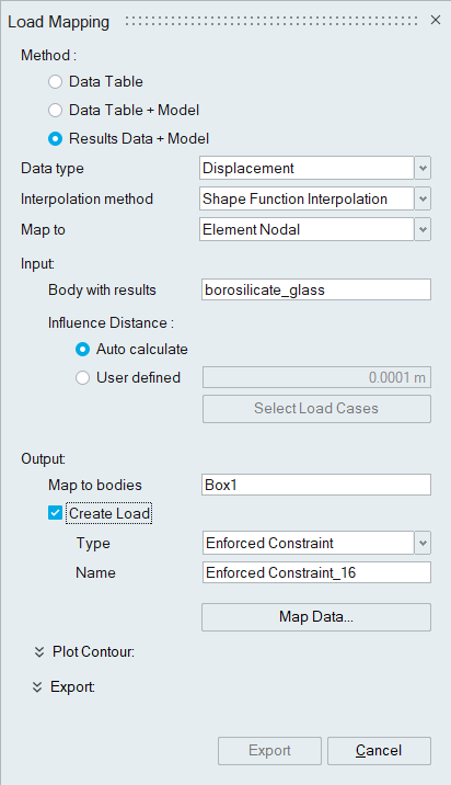
- Data type:
Option used to select the type of load to be mapped. This determines the number of data that needs to be mapped.
For Displacement, displacement along X,Y,Z and resultant will be mapped.
For Stress, stress components will be mapped.
For Strain, strain components will be mapped.
For Temperature, temperature values will be mapped.
For Nodal Force, nodal force values will be mapped.
For Heat source density, heat losses will be mapped.
- Interpolation method:Option used to select the mapping algorithm.
- Shape Function Interpolation: The mapping is done based on Element Shape function parameters.
- Force Balance: This method distribute the forces in the reference mesh to the new mesh without altering the force balance equilibrium. This method is applicable only for data type - force.
- Map to:
Option to select the reference (Element Node/ Element Centroid) considered for mapping.
For surface based loads, its better to use Element centroid approach.
For node based loads, Element Nodal is a better approach.
- Body with results:
Option used to select the Results Model/Body.
- Influence distance:
Option used to specify the search limit - This is the tolerance within which the input data for each node will be considered for mapping.
Auto Calculate will determine the search limit based on the average element size.
- Select Load Cases:
Option to select the load case for which the results mapping needs to be carried out.
- Map to bodies:
Option to select the model/body to which the results data needs to be mapped.
- Create Load:
Option to create loads automatically with the output data of the mapping.
Data type Load Displacement Enforced displacement Stress Initial stress Temperature Temperature Force Force Heat source density Heat source Note: Load can be created when mapping done from a single loadcase.
Plot Contour
Options to plot contour for the mapping outputs are available.
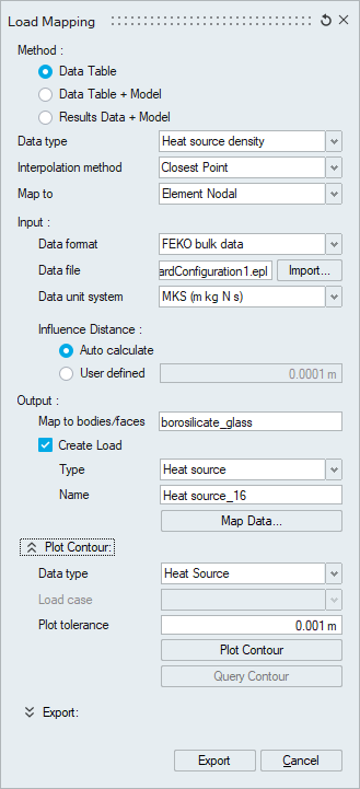
Contour will be displayed based on the display unit system
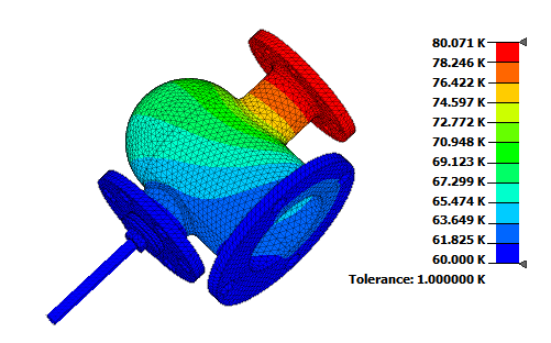
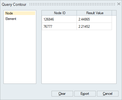
Also an option to query the contour plot values is available. If Query Contour is selected, a separate dialog will pop up with options to query the contour plot by picking nodes (or) elements.
Export
- X, Y, Z, Value
- Node Id, Value
- Elem Id, Value.
- Elem ID, Node ID, Value
- OptiStruct format (.pch)
- Abaqus format (.inc)
- Fe-Safe format (.dat)
The ouput file can be of CSV-Comma Separated Value format (or) Tab De-Limited format.