Orient Bar2 or Bar3 Elements
Use the Edit Beam: Orient tool to define bar2 or bar3 orientation.
Each solver profile manages beam orientation in a different way and provides more or less flexibility to define orientation, such as vector or third node. However, despite such variability in the way solver realizes orientation, the context options remain almost unchanged and hide the complexity. However, if an option is irrelevant for a given solver, it will be hidden.
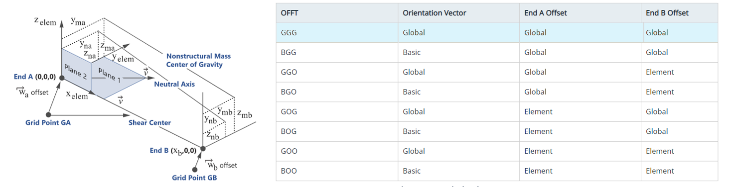
Although HyperMesh has a Global system (system ID=0), some solvers (for example, OptiStruct/Nastran) use global to denote the node's output system and use Basic to refer to laboratory global system. Basic and Displacement are used for the laboratory reference system or the node output system in which displacement components are written.
-
From the 1D ribbon, click the tool.
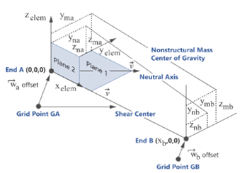
Figure 2. 
- Select elements to orient.
- Optional:
On the guide bar, click
 to define orientation options.
-
Orient using a reference node, clear the By Vector check
box.
-
Orient using a reference element, clear By Vector check
box.
-
Orient using a vector as a method.
- Select the By Vector check box.
- Use the options in the microdialog to orient.
Option Description Orient Bar2/Bar3 as Plate Stiffener Click  to align the bar2/bar3 vertical axis along
the positive normal of an adjacent shell.
to align the bar2/bar3 vertical axis along
the positive normal of an adjacent shell.Normals of adjacent shells are averaged since they do not have an angle greater than the threshold value (break angle) defined in the options. For sharp angles, the shell with the lowest ID is used as a reference. In the case of T-junctions, you can select a reference shell by hiding undesired shells and by setting the "Normal from shells" option to Displayed.
Rotate Elements Along the X-Axis  - dynamically rotate Plane 1 using a
manipulator. The same rotation angle will be applied to element
selection from their original orientation.
- dynamically rotate Plane 1 using a
manipulator. The same rotation angle will be applied to element
selection from their original orientation.Click
 in the microdialog to expose the
incremental option.
in the microdialog to expose the
incremental option.Vector Tool and Systems Provide an arbitrary orientation vector in space using the Vector tool. - Click
 .
. - Orient the vector then press Esc to return to the current tool.
In the manipulator microdialog, you can select a local system to resolve vector coordinates. Click
 to pick a
system.
to pick a
system.Use the vector manipulator or enter x, y, z components (resolved in local system).
Orient in Displacement System Define orientation vector components in Node1’s output system. - Click in the
Orient microdialog to expand the
microdialog.
- Enter X, Y, Z components of orientation vector in displacement system.
Restriction: This option is not available for all solver profiles.Replace Orient by Vector In case the beam uses a node for orientation, use this option to replace the node with an equivalent vector. The vector goes from the beam node 1 to the orientation node. Click
in the Orient
microdialog then select
Replace orient by vector.If you select a beam that has no node, the option does nothing.
Restriction: This option is only available in solver profiles which natively support orientation by vector.
- The orientation direction defines the XY planes. Hence, whenever orientation is set along shell normal, theY-axis matches with shell positive normal as a result.
- All orientation methods, but picking reference node result on X,Y,Z orientation vector, are saved at element level.
- Using the Orientation by Vector tool (with or without system) will assign the OFFT key for orient as B. This means components are expressed in Basic system, see Figure 3.
- Using Orientation in displacement system will set OFFT for orientation as G, see Figure 3.
- Replace Orient by vector is available.
- The orientation direction defines the XZ planes. Hence, whenever orientation is set along shell normal, the Z-axis matches with shell positive normal as a result.
- All orientation methods result in the creation or update of a third node on each bar2/bar3. Hence, there is no concern of Basic/Displacement system.
- Replace Orient by vector is not available as it is meaningless.