Update Beam Elements
Use the Section Property tools to update properties assigned to bar2 elements (target) using a cross section on various entities as the source.
- A collection of solid geometries
- A collection of surfaces
- A collection of elements (2D & 3D)
-
From the 1D ribbon, click the appropriate
Section Property tool.
Figure 1. 
Use the arrow to the right of the tool icon to select the type of beam section to update.
- Elastic section
- Shell section
- Solid section
- VABS section
- Select Update beams from the drop-down on the guide bar
Elastic/Solid Section
This configuration calculates material weighted moments of inertia considering Young's modulus and the Poisson ratio of each intersected entity. Support is currently limited to isotropic materials with card image MAT1. Gaps between domains are also supported and solved by contact between disconnected regions.
-
Select 1D elements to update.
Selection is filtered to retain only valid elements (bar2). Moreover, for OptiStruct and Nastran, a further filter is performed on element types to retain only CBAR/CBEAM elements.
-
Select source elements.
Sources are the entities intersected with a plane used to calculate sectional properties. Valid sources types are:
- Solids
- Surfaces
- Elements
For elastic sections, if surfaces or 2D elements are selected, then the intersection with a plane (lines) is inflated using local thickness. It is mandatory to have a valid property with a thickness value assigned to sources. In the case of surfaces, it must be done at the component level.
Moreover, the source entities' materials are used to evaluate material weighted sectional properties. As specified in Default Material, if a material is not available for a region, the default is used.
-
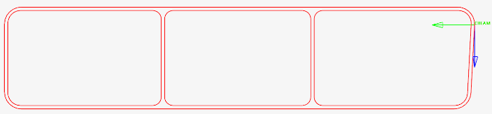
Use the first icon menu in the microdialog to define
plane locations and where intersections are generated on source elements.
Figure 2. Section Cut: a) Single cut b)Per element c)Per node 
- Single cut
-
Update a list of elements with a single property extracted from a single user-defined location. Click
 to define the cutting plane.
You can adjust the base point and plane normal. Placing the
cutting tool on a target element will adjust the plane’s
normal along the selected element’s X axis.
to define the cutting plane.
You can adjust the base point and plane normal. Placing the
cutting tool on a target element will adjust the plane’s
normal along the selected element’s X axis.A single preview shows intersections before proceeding. Changing the source updates the preview.
The reference point (see Orientation and Offset) is the intersection of the cutting plane with a target element. This defines the reference orientation and offset.
If you perform a section cut using a plane which does not intersect any of the target elements (Figure 3), then the reference point is extracted from the plane's base point.
You need to pay attention to the local normal and relative position of the manipulator in the section cut to obtain accurate result to assign to its target selection. Target elements must have consistent orientation.
-
Figure 3. Single cut out of targets 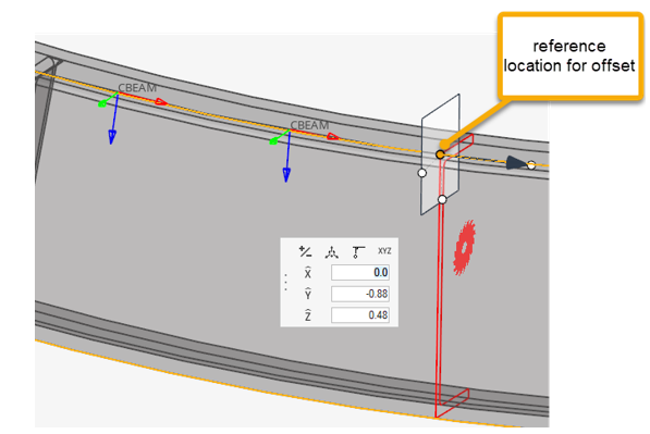
- Cut per element
- Automatically perform a section cut on each target element. As
explained in Orientation and Offset, the resultant section is valid per element no matter its
orientation. The intersection is done by default on the midpoint
of the target element. You can set a value (0 to 1) to specify
the parametric position between the target element’s nodes
(Figure 4). The orientation can’t be changed. The
plane is normal to the target’s X axis.
Since a cut is performed per element, all meshing processes and calculations are done as many times as target elements selected. This is obviously more time consuming than a single cut. Whenever a region of multiple targets share the same section, it is advisable to use the Single Cut method to reduce computation time.
However, it is possible to consolidate and reduce the number of beam sections created if they fall within the same range of values. Associated properties can also be consolidated. These options are accessed from the guide bar menu (
 ).
). -
Figure 4. Intersection at 30% resp. 80% of each element 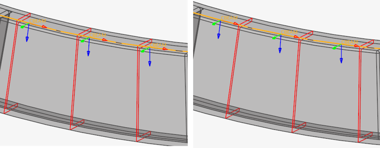
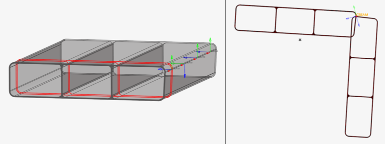
- Cut per node
- A cut is performed on each node of the target elements. If adjacent elements form a vertex angle between their X axis below the threshold angle tolerance, a single cut is done for common nodes; otherwise, one cut per element is performed at the same node using different normal. No additional test is done on (Y,Z) axis deviation from adjacent elements. Properties will be created with two beam sections: one at each end station. If a single cut is done on a node, the two adjacent properties share the same beam section for their relative station.
-
Click
 in the microdialog to
toggle between a finite and infinite plane.
in the microdialog to
toggle between a finite and infinite plane.
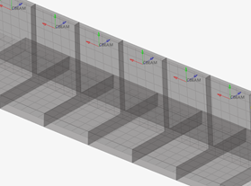
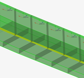
In some situations, it is best to consider a finite plane to intersect sources. In the Figure 5, using the (default) infinite planes would result in undesired regions considered during trimming. In such cases, you can switch to a finite plane and define the width and height of the section cut. However, it is not possible to define the size location per location. The width and height will be common for all intersections.
Figure 5. Finite size planes 
-
Use the second icon menu in the microdialog to choose
between offsetting or translating the beams.
Translating will actually translate beam nodes to match the source and can be done to the shear center or the centroid.
Figure 6. Beam offset 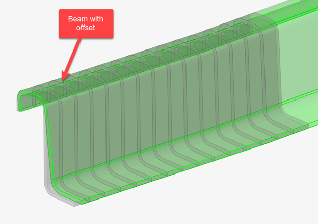
Figure 7. Beam translate 
-
Click on the guide bar to define
options such as:
- Whether or not to create a link a sketch entity to the beam section
- A tolerance for filling small gaps between lines
- Contact management: See Disconnected Parts for more information.
- A default material for regions without a valid material assigned
- Section consolidation
- Section cleanup will remove an area of the section that may have been captured unintentionally.
- Optional:
For Elastic sections, select a target material.
If the "Ignore source material" checkbox is turned off below the guide bar, a homogenized material is automatically generated and assigned to the property unless you select a target material to be used in normalization.
If the option "Default material" is set to "User", then the material selector on the guide bar is a mandatory.
Otherwise, if the checkbox is turned on, the material is optional and simply assigned to the property with no impact on the beam section.
Refer to comments in Sectional Property Evaluation Theory regarding the normalization of sectional properties using material to obtain correct stiffnesses.
-
Click
 .
.
The sectional properties calculation is launched. When the process is done, a review of the calculated sections is shown. Properties are created based on the element configuration and assigned to elements. Offset is applied to target elements. Material and beam sections are generated per property.
The review considers real section shapes (after inflates) as well as offsets.
Figure 8. 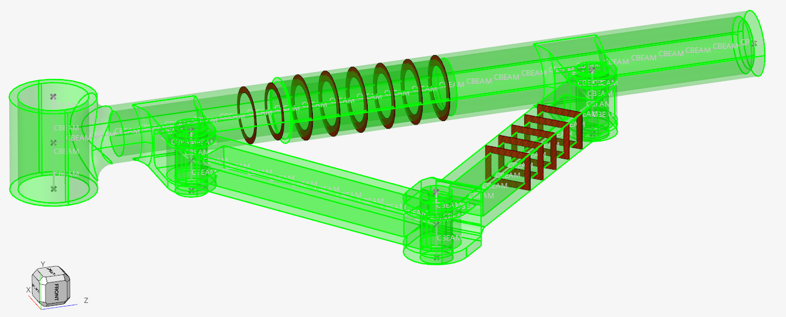
Sectional Property Evaluation Theory
The Section Property tool calculates the intersection between a plane and source entities. It can be a plane per 1D target element or a single cut at a user-defined reference location.
 |
 |
 |
 |
Material info is considered from each intersected entity. If source entities intersected are solids or surfaces, then the material is extracted from the component which holds the intersected geometry. If source entities are elements, then material info is gathered from each element (directly or through component).
Sectional properties are hence calculated following theory as described in: “Analysis and Design of Elastic Beams: Computational Methods, Walter D. Pilkey”
The material neutral axis is calculated along with stiffness terms EIyy, EIzz, GJ, and EA considering local material info. Shear Center and warping properties like torsional constant and warping constant are also calculated.
After sectional properties are calculated accounting for all isotropic materials, a regular homogeneous beam property is created referring to a single (homogenous) material and an elastic beam section. Regions without a material assigned or with non-isotropic materials (card image other than MAT1) raise a warning. If you continue, such regions will have a material assigned following the “Default material” rule set in the options menu.
You can specify a target material to be used for homogenization or let the tool auto-calculate the material property using effective young modulus. The beam section area and area moments of inertia are set based on the material's Young's modulus to retrieve the same stiffness terms as calculated from the intersected entities.
In turn, if the material is auto-generated, its young modulus is derived from the section product EA and total area A as Eeff= (EA)sec/A. The area moments of inertia are then I=EI/ Eeff; Moments of inertias will deviate from geometric quantities in case of multiple materials, but the section’s Area is correct.
If a target material is provided, then its young modulus will be used; hence all geometric terms A, Iyy, Izz, Iyz may deviate from those calculated by closed form equations for similar geometric shapes.
Orientation and Offset
The elemental system of target 1D elements remain unchanged during the update process.
When a cross section is performed on a 1D element, its local X axis is taken as the section plane’s normal. The beam section local 2D system (Y, Z) matches with the elemental axis (Y, Z). Sectional properties are hence valid in elemental system as defined. If orientation needs to be adjusted, it is advisable to update the element orientation first (see Orient Bar2 or Bar3 Elements).
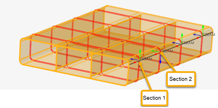
Since a cut is performed per element in Figure 13, each section has its own local system matching the elemental system, as shown in Figure 14 & Figure 15. The origin of the system, from which Centroid and Shear Center coordinates are saved in the beam section entity, is taken at the center of the bounding of the section in the local system.
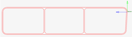
After proceeding, a 3D detailed visualization of updated beams shows the resulting beam cross section taking into account orientation and offset.
Default Material
If the “Ignore source material”checkbox is turned off and all regions have a valid isotropic material, then this option has no effect. Otherwise, if some materials are missing or invalid, there is a provision to auto-assign default materials to such regions.
- Max
- The material with the greatest Young's modulus (among those found in the intersection) is assigned to these regions.
- Mean
- The arithmetic average of the Young's modulus and the Poisson ratio of other materials found in the intersection are considered. This is a simple average of materials without accounting for the number of occurrences.
- Nearest
- The material from the nearest region with a valid material is used.
- User
- A user material is used. This implies that the material selector become a mandatory selection and in turn the user material is used for normalization.
However, using such a default is not a good practice in general; you should assign the proper material to account during section cut.
Disconnected Parts
A section cut on a model may lead to disconnected regions. It could be because of separate bodies which are glued or welded, or because section undergoes a hole in model. A valid section needs to be connected to consider it as an equivalent beam section.
In any case, the Section Property tool generates a beam section with geometric properties like area and second moments of inertia calculated. However, to fully complete the process and calculate shear center position as well as torsional & warping constants, the section need to be “connected”.
The tool provides an option called “contact”.
- Best match - Search contact between domains based on internal tolerance calculated from local mesh size.
- Tolerance - Search contact between domains based on user defined tolerance.
- No contact - No contact searches.
After gluing domains, sectional properties are calculated as described above.
Consolidation
An option for the consolidation of beam sections and properties is available. It is valid when you cut large prismatic solids where properties do not vary a lot. Hence, it reduces the number of beam sections created.
- Area
- Section's Modulus
- Torsional constant
If any of these metrics deviates more than the threshold tolerance given, then a new beam section is created.
Shell Section
This configuration calculates area moments of inertia considering thinwall theory and uses HyperBeam engines. An option for auto-weld is available to reconnect disconnected domains by spot welds.
-
Select 1D elements to update.
Selection is filtered to retain only valid elements (bar2). Moreover, for OptiStruct and Nastran, a further filter is performed on element types to retain only CBAR/CBEAM elements.
-
Select source elements.
Sources are the entities intersected with a plane used to calculate sectional properties. Valid sources types are:
- Surfaces
- 2D Elements
It is mandatory to have a valid property with a thickness value assigned to sources. In the case of surfaces, it must be done at the component level. Entities without thickness are filtered out from the selection.
- Use the first icon menu in the microdialog to define plane locations and where intersections are generated on source elements.
-
Click on the guide bar to define
options such as:
- Whether or not to create a link a sketch entity to the beam section
- A tolerance for filling small gaps between lines
- Whether or not to weld disconnected part flanges
- Section consolidation
- Section cleanup will remove an area of the section that may have been captured unintentionally.
- Optional:
Select a target material.
The material is optional and simply assigned to the property with no impact on the beam section.
-
Click .
The sectional properties calculation is launched. When the process is done, a review of the calculated sections is shown. Properties are created based on the element configuration and assigned to elements. Offset is applied to target elements. Material and beam sections are generated per property.
The review considers real shell sections as well as offsets after auto-weld if the option is turned on.
VABS Section
This setting is available for the OptiStruct profile only. It creates OptiStruct PBEAML using the VABS file generated by the tool from each intersection with composite shell model.
-
Select 1D elements to update.
Selection is filtered to retain only valid elements (bar2).
-
Select source shell elements.
Sources are the entities intersected with a plane used to calculate sectional properties. It is mandatory to have a valid composite property assigned to sources.
-
Click on the guide bar to define
options such as:
- The folder where the VABS files generated per beam element are created
- A debug flag to create true HM elements that represent plies intersection.
-
Click .
The mesh inflate from plies is launched. When the process is done, a review of the sections is shown. VABS *.dat files are created in the folder set in the options.
A property PBEAML referring to each VABS file is created per element and assigned to the element.
After existing the tool, the section visualisation is lost.