Create Member Mesh
Use the Member Mesh tool to create 1D elements on edges, free lines, nodes, or members.
Use the Member Mesh tool to create the following elements:
- Bar2/Bar3
- Rods
- Line Mesh (for bar2 and rod elements only)
-
From the 1D ribbon, click the Member
Mesh tool.
Figure 1. 
Note: The Member Mesh tool is in a tool group with Stiffener Mesh. Click the arrow to the right of the icon to cycle between the two. - On the guide bar, use the first selector to choose either Lines, Members, or Node List.
-
Set or change meshing/orientation/organization options by clicking
 on the guide bar.
-
Select source entities.
When you select lines, there is an automatic sort according to the following rules:
- Free lines – all lines are meshed as though the line mesh panel was behaving with default orientation derived from the line's Frenet frames.
- Unmeshed edges – seed based on size/density/biasing like orphan lines, but default orientation follows the local surface normal.
- Meshed edges – meshing behavior depends on the value of the Reference
shells option:
- None: sample elements along lines based on mesh size/density. Orientation depends on options.
- Displayed: seed element along shell edges irrespective of density/size set. Orientation and offset derived from displayed connected shells.
- All: seed element along shell edges irrespective of density/size set. Orientation and offset derived from all connected shells.
For edges and nodes, mesh is honored if the reference shells option is set to displayed or all. If it is set to none, mesh density is honored even if there is shell mesh.Figure 2. Seed, Orient, and Offset Beams from Displayed 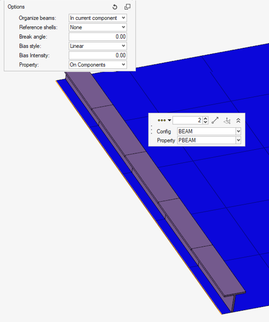
Figure 3. Seed Based on Size, Orientation from Line 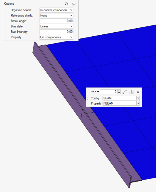
-
Select meshing parameters and biasing options.
- Optional:
Create bar3 or bar2 element when it applies.
Note:
- If mesh follows shell edges, the order is given by the adjacent shells.
- If mesh is done on free lines, elements bar2/3 are created based on this selection.
- This option is not available in all solver profiles.
- Optional:
Select an orientation vector and apply it to all newly created elements.
- Click
 in the microdialog to
orient using the Vector then click
in the microdialog to
orient using the Vector then click  . After defining the orientation vector, press
Esc to return to the
current tool.
. After defining the orientation vector, press
Esc to return to the
current tool. - If neither of the icons are activated, the orientation will follow default orientation. This may vary based on the solver profile.
- Click
- Optional:
Using the second selector on the guide bar, assign
either a property or beam section to the selected elements.
See the Restrictions below.
-
On the guide bar, click one of the following:
 - Save changes and stay in the tool.
 - Save changes and close the tool.
The engineering type and, if available, the property card selected in the microdialog filters the list of available candidates for beam
section or property entity selectors in the guide bar. It
also drives the mapping of element config/type vs property card image. The mapping
rules vary depending on each solver profile.
Restriction: For the
OptiStruct and Nastran profiles only:
- ROD engineering config only keeps PROD property card image.
- Elements are created as CROD elements with PROD property.
- Property selector filters only existing PROD properties.
- BEAM engineering config keeps only PBAR/PBARL and PBEAM/PBEAML.
- Elements are created either as CBAR or CBEAM elements based on the property card.
- Property selector filters based on the selected card.
- If a beam section is selected, a property is created with the selected card image.
- PIPE engineering config keeps only PTUBE.
- Elements are created as CTUBE.
- Property selector filters PTUBE.
- Beam section selector filters standard beam section TUBE.
- If a beam section is selected, element type and property card are driven from the microdialog. If PBEAML/PBARL are selected but the beam section is not valid, the respective PBEAM/PBAR is created.
Restriction: For ANSYS
profile only:
The default element type (ET) created based on each engineering config is shown in options. Properties are created with card image SECTYPE and relevant ET Type and Section entity associated.
- ROD engineering config:
- Property selector filters only existing properties.
- With card image SECTYPE.
- With referenced Section entity with card LINK.
- If beam section is selected:
- Section entity is created with config LINK with area copied from the beam sections area.
- Property entity created with card SECTYPE and refers to Section entity.
- Elements are created with ET LINK180.
- Property selector filters only existing properties.
- BEAM engineering config:
- Property selector filters only existing properties.
- With card image SECTYPE
- With referenced Section entity with card BEAM.
- If beam section is selected:
- Section entity is created with config BEAM with reference to beam section.
- Property entity created with card SECTYPE and refers to Section entity.
- Elements are created with ET BEAM188 or BEAM189.
- Property selector filters only existing properties.
- PIPE engineering config:
- Property selector filters only existing properties:
- With card image SECTYPE
- With referenced Section entity with card PIPE
- Beam section selector filters beam section CTUBE:
- Section entity is created with config PIPE.
- Diameters are copied from selected beam section.
- Property entity created with card SECTYPE and refers to Section entity.
- Elements are created with ET PIPE288 or PIPE289.
- Section entity is created with config PIPE.
- Property selector filters only existing properties: