Create Beam Sections from Entities
Use the Section Property tools to create Shell, Solid, or Elastic sections from model entities.
Use the arrow to the right of the tool icon to select the type of beam section to create.
- Elastic section
- Shell section
- Solid section
Shell Part Thickness
Shell beam sections are geometrically defined by segments (grouped inside parts) with thickness assigned to each part. Elastic sections can by made of Solid parts as well as Shell parts.
In the following sections, whenever we define a Shell part (whether thinwall or Elastic engine) we fill-in a thickness value for this part.
- Automatic uses 10% of the global mesh size.
- Manual lets you set your own thickness.
Entities such as lines/surfaces or 1D elements extract thickness from the component where they reside. So components need to have a valid property assigned.
Context Options
Click ![]() on the guide bar to access the following
options:
on the guide bar to access the following
options:
- Create Sketch
- Create and link a sketch along with the beam section.
- Merge tolerance
- Fill-in small gaps between lines below this tolerance.
Shell section options
- Autoweld
-
- No weld: do not attempt to weld disconnected parts flanges.
- Force: try to force welds between flanges of a part. This is subject to part thickness versus gap.
Solid section options
- Order
-
- First: create first order mesh for solid section.
- Second: create second order mesh for solid section.
Elastic section options
- Contact
-
- Best match: search for contact within a tolerance that's 80% of the section’s mesh size.
- No Contact: do not search for contact.
- Tolerance: Provide a user-defined tolerance to search for contact.
- Material
- Decides how to assign material in region without material.
Create Beam Sections from Planar Entities
- Select Planar entities from the guide bar drop-down.
-
Select source entities.
Entity selection aims to define the geometric shape of the section. Parts are split based on rules depending on the beam section type.
Option Description Shell beam section - Change the selector type to Elements.
- Select elements in-plane that represent the thinwall section you want to create.
- Only plotels, bar2, and rod elements are kept (Figure 2).
- Alternatively, change selector to Lines
and select lines that define a section.
- FE Topology lines are supported.
Figure 2. Create shell from 1D elems with default plane 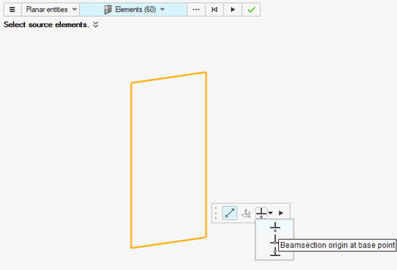
Solid/Elastic beam section - Change the selector type to Elements.
- Select elements in-plane that represent the solid section you want to create.
- Only shell elements are kept.
- Alternatively, change selector to Lines
and select lines that define a section.
- Solid sections are created as the surfaces generated from the lines contour.
- If nested contours are found, then they are considered as holes (Figure 3).
- Alternatively, change selector to
Surfaces.
- Select in-plane surfaces that represent the solid section you want to create.
- FE Topology surfaces are unsupported and ignored in the selection.
Figure 3. Solid section from nested loops (View in HyperBeam) 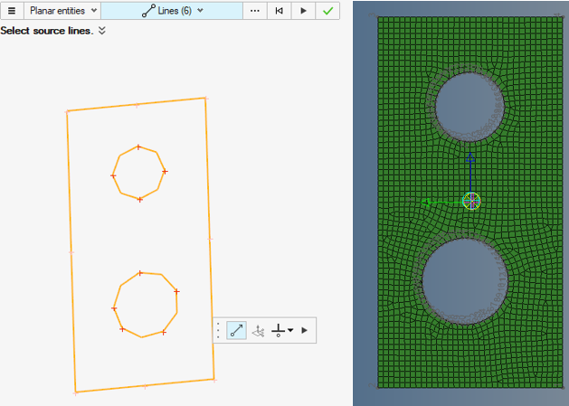
Elastic beam section - The same entities as Solid sections are supported for Elastic sections.
- Choose whether to consider or ignore materials.
- Change the selector type to Elements.
-
Set the plane and orientation.
Option Description Automatic orientation Make sure that  is turned on in the microdialog.
- The tool infers the best plane from the input selection.
- Entities lying off-plane are projected on plane along the normal.
User-define plane and orientation Turn off then select the plane manipulator  .
.- Pick any entity on screen to initialize the base point location.
- The plane normal is initialized as per the calculated Automatic plane.
- Pick the normal handle or use the microdialog to define a normal vector (Figure 4).
- To adjust the base point, use the manipulator base handle. For precise control of the base, use the Move tool in the microdialog (Figure 4) and adjust the X,Y,Z location (Figure 6).
- While in Move tool, use the in-plane rotation to adjust the green axis. This will define the section’s Y axis (Figure 6).
- Entities off-plane are projected on selected plane along the normal.
Figure 4. Normal and base 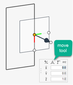
Figure 5. Adjust the base point 
Figure 6. Section's vertical axis 
Tip: Orientation tips:- Beam section 2D space is considering (Y,Z) axis, assuming X as inward normal (screen depth). This was done to match with the beam elemental system where the X axis is along Ga → Gb.
- Sketch plane is using (X,Y) plane with outward normal Z.
- The manipulator is also displaying Normal like Z axis.
The recommendation is to always plane normal inward from the selection while selecting the Y axis of the manipulator as the desired vertical axis in beam section space. Hence, proper transformation is done. See Figure 7, which illustrates manipulator selection and the resulting sketch and beam section.
While assigning a sketch (defined in an X,Y plane) to a beam section, there is always a transformation done so the Y axis remains as-is. The sketch X:Z axes are swapped then one axis is flipped to maintain a direct system following right-hand side rule.
Figure 7. Sketch orientation 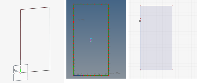
-
Select a beam section center location from the drop-down in the microdialog.
- Base points
- Aims to use the plane base point as the beam section’s origin.
- Centroid
- Uses calculated centroid as the beam section's origin.
- Shear center
- Uses calculated shear center as the beam section's origin.
If a Sketch is created, this origin option is reflected in beam section dataname Center in the Entity Editor.
-
Click
 .
A beam section and, if selected, a sketch are created.
.
A beam section and, if selected, a sketch are created.As explained before, there are reference system discrepancies between beam section and sketch entities.
In order to maintain axis consistency, a Sketch is created with an opposite Normal/X axis from the selection. Sketch datanames are populated as below:- Plane Origin: use plane base
- Plane Normal: use opposite value from selected plane normal
- Plane X axis: use opposite value from selected plane X
Create Beam Sections from Section Cuts
- Select Section cut from the guide bar drop-down.
-
Select entities to intersect with a (finite or infinite) plane.
Option Description Shell beam section - Change the selector type to Elements.
- Select elements to intersect with a plane
- Only shell elements are kept.
- Alternatively, change selector to
Surfaces and select surfaces to intersect.
- FE Topology surfaces are supported.
- There is no direct selection of solid entities since only surface skins are considered.
Shell or surface intersections with the plane define lines that form shell parts.
Solid/Elastic beam section - Change the selector type to Elements.
- Select elements to intersect with a plane
- Shells and 3D elements are kept.
- Alternatively, change selector to
Surfaces and select surfaces to intersect.
- FE Topology surfaces are supported.
- Alternatively, change selector to Solids
and select solid geomtry.
- FE Topology solids are supported.
The intersection of surfaces or 2D elements with the plane forms lines. Closed loops are filled to form surface regions. The intersection with 3D mesh or solid geometry directly provides surfaces.
Elastic beam section - The same entities as Solid sections are supported for Elastic sections.
- Choose whether to consider or ignore materials.
- Change the selector type to Elements.
-
Define the cutting plane.
-
Click
 in the microdialog
to toggle between a finite and infinite cutting plane.
in the microdialog
to toggle between a finite and infinite cutting plane.
-
Click .
Three initial planes are displayed that align with global axes. Plane size is based on the displayed entities.
-
Click
-
Adjust the plane's dimensions as needed.
-
For more precision, click .
Figure 8. Section cut manipulators 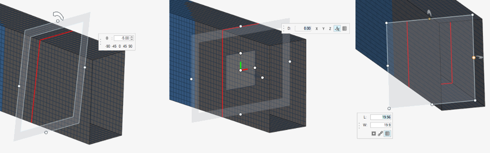
Tip: Orientation tips:The same explanation as for creating beam sections from planar entities is still valid:
- Beam section 2D space is considering (Y,Z) axis, assuming X as inward normal (screen depth). This was done to match with the beam elemental system where the X axis is along Ga → Gb.
- Sketch plane is using (X,Y) plane with outward normal Z.
- The manipulator is also displaying Normal like Z axis.
The recommendation is to always plane normal inward from the selection while selecting the Y axis of the manipulator as the desired vertical axis in beam section space. See Figure 7, which illustrates manipulator selection and the resulting sketch and beam section.
-
For more precision, click
-
Select a beam section center location from the drop-down in the microdialog.
- Base points
- Aims to use the plane base point as the beam section’s origin.
- Centroid
- Uses calculated centroid as the beam section's origin.
- Shear center
- Uses calculated shear center as the beam section's origin.
If a Sketch is created, this origin option is reflected in beam section dataname Center in the Entity Editor.
-
Click .
A beam section and, if selected, a sketch are created.
As explained before, there are reference system discrepancies between beam section and sketch entities.
In order to maintain axis consistency, a Sketch is created with an opposite Normal/X axis from the selection. Sketch datanames are populated as below:- Plane Origin: use plane base
- Plane Normal: use opposite value from selected plane normal
- Plane X axis: use opposite value from selected plane X