Convert Beams to Equivalent 2D Shell Mesh or 3D Solids
Use the Inflate tool to create 2D shell mesh or 3D solids from 1D beams.
- Surfaces
- Shell Mesh
- Solids
It also supports options to create surfaces/mesh congruent with beam nodes.
-
To convert to 2D shell mesh/surfaces:
-
From the 1D ribbon, click the
Inflate tool.
Figure 3. 
-
On the guide bar, click
 to define various
options.
to define various
options.
Option Description Generate surfaces from beams but not 2D elements - Select Surface only.
- Click
 to create
surfaces and remain in the tool or click
to create
surfaces and remain in the tool or click  to create
surfaces and exit the tool.
to create
surfaces and exit the tool.
Generate surfaces and 2D elements from beams - Clear the Surface only check box.
- In the microdialog, select the element size and type for the shells.
- Click in the microdialog.
During surface extraction, the thickness is mapped to surfaces but properties are not created directly from this tool.
-
From the 1D ribbon, click the
Inflate tool.
-
To convert to 3D solids:
-
From the Mesh ribbon, click the
Beams to Solids tool.
Figure 4. 
-
On the guide bar, click to define various
options.
-
Click to create solids and
remain in the tool or click to create solids and
exit the tool.
-
From the Mesh ribbon, click the
Beams to Solids tool.
Options
Reference Point
- Section shear center
- Consider beam node matching the section’s shear center.
- Section centroid
- Consider beam node matching the section’s centroid.
- Beam node
-
- Valid only for some standard sections, such as Channels (C, U) L, T (and variants) Bulbs, I.
- The shape is positioned congruent with beam nodes no matter what the exact offset value if beams are connected to shell elements. The offset along the element normal places created surfaces on the correct side.
- Whenever this option is set, the resulting mesh is connected to the beam node; mesh size is honored only in remaining edges trying to achieve a panel mesh.
Surface Continuity
- Path vertex angle
- Threshold vertex angle between adjacent beams under which surfaces are interpolated.
- Orientation tolerance
- Threshold angle between local Y axis of adjacent beams under which surfaces are interpolated.
- Shell parts
- How to generate surfaces from shell beamsection parts (see further explanation).
Destination
The destination defines where surfaces/shell mesh is created. It can be different for standard and shell beamsections, as the later offers more options.
Shell destinations include:
- Current component
- Use current component.
- Beam component
- Create surface/shell mesh in a 1D beam component.
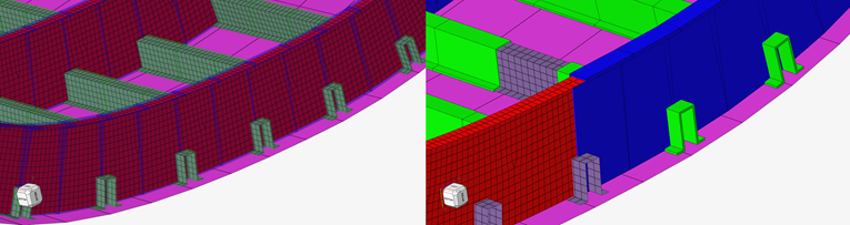
- Split by part
- Create components using the part of the shell beamsection with same name as the part name.
- Split by part thickness
- Create components using the part of the shell beamsection with the same name as the part name_partthickness.
- Thickness
- Option to capture thickness or not during conversion.
Comments
- Nodal thickness defines the thickness directly on each element card.
- Properties are created and assigned at the element level, except if all elements belonging to a single component share the same thickness; in this case, the property is assigned to the component.
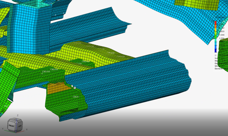
- Tapered beams are supported both for standard and shell beamsections. Smooth surfaces are created between stations.
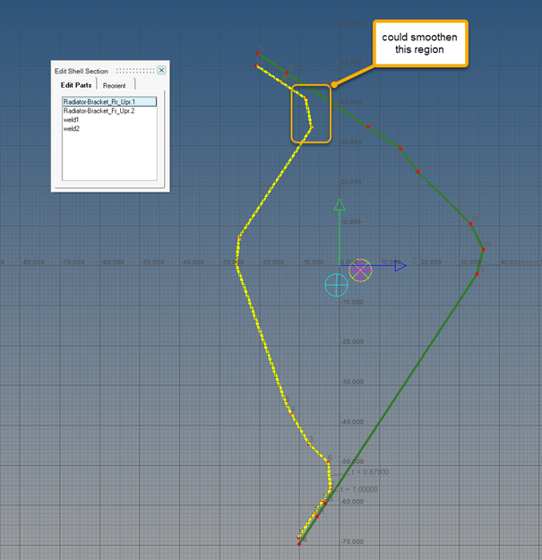
Further Explanation of Shell Beamsections
Shell beamsections are a collection of parts with a name. Parts with the name weld* are ignored.
Parts are a collection of ordered vertices. Lines are first generated by parts either as straight segments or smooth lines and used to create surfaces from station to station.
- Whether straight segments are created from points
- If a smooth line is generated while keeping straight regions if more than two points were originally aligned.