Offset Bar2 and Bar3 Elements
Use the Edit Bar2 and Bar3 Offset tool to manually set offsets or adjust beams on plates.
- Element topology (2 or 3 nodes)
- An orientation method aiming to define the element system
- A cross section with section properties
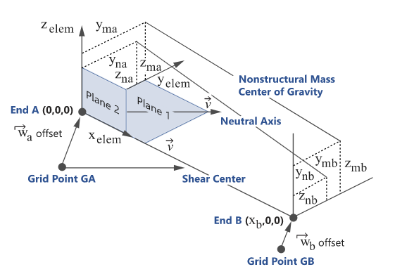
- Defined by a Centroid (or Neutral axis) and Shear Center
- Defined in a local 2D system (YZ plane) with Origin
- A reference point that matches with the element’s node
- Optional offset
- Shift the default reference point to a certain amount
- Some solvers support offset at element level while some others define offset at section’s property level (assigned to multiple elements).
- Some solvers can define different offsets at each end of a beam while others may limit to a constant offset.
- Offset components could be defined in various systems.
- Default reference point and sign convention may change depending on solver.
However, despite such variability in the way solver realizes offset, the context options remain almost unchanged and hide the complexity.
-
From the 1D ribbon, click the tool.
Figure 2. 
- Select the elements in the model you want to offset.
- Optional:
On the guide bar, click
 to define offset options.
-
Select an offset method using the options in the microdialog.
Option Description Offset on Plates Automatically offset a beam element. A element can be connected to either a single element's edge or can be shared between two elements at a plate T-junction. The Adjust to shell tool will consider a shell's thickness and offset during offset calculations. In the event of a sharp angle or T-junction, you can position the beam in four different quadrants.
While performing an offset, you can choose whether the adjustment is done on both normal and lateral directions. A normal offset means that the offset is along the element's axis in Plane 1, while a lateral offset is along the element's Plane 2 axis. In the case of a free edge or T-junction, the beam is adjusted such that its bounding box matches with the edge.
Similar to the Orient tool, options determine which shells are considered during the adjustment. They also handle thickness variations between adjacent plates. If the Thickness method option is not set to Averaged, the shell with the minimum (resp. maximum) thickness is used as a reference and adjustments are performed on this shell element.
- Click
 .
. - Use the drop-down menu below to choose the direction of adjustment. This can be either Normal and Lateral, Normal, or Lateral.
- Select the appropriate quadrant from the following:
- Positive base and adjacent
- Negative base and positive adjacent
- Positive base and negative adjacent
- Negative base and adjacent
Match Grid with Centroid/Origin Click  to apply offset so the beam Center matches
with the grid.
to apply offset so the beam Center matches
with the grid.Click
 to apply offset so the beam section
Origin matches with the beam.
to apply offset so the beam section
Origin matches with the beam.This is useful for shell or solid sections where a reference point needs to be honored.
Reference Element Click  and select a reference element. The same
elemental offset is applied to the destination.
and select a reference element. The same
elemental offset is applied to the destination.Elemental YZ Manipulator Use the elemental YZ manipulator as an incremental offset manipulator in elemental systems. The elemental YZ manipulator acts on the whole selection of beam elements. Each manipulation along the Y or Z-axis will append that amount to every selected element regardless of their current offset value. This tool is not meant to assign the same resulting offset value to all selected elements. Instead, the selected elements will be updated by the exact same increment.
- Click
 .
. - Use the Y and Z manipulators to manually adjust the offset.
- PressEsc to return to the Offset tool.
Offset Components Fine tune offsets by components. You can fine tune offsets in both the displacement system and the elemental system for solvers where available. Typically this is done when you need to update a large selection of elements.
- Click
 .
. - Enter the appropriate X, Y, and Z offset values and press Enter.
Match with Shear Center Click  to apply offset so the beam Shear Center
matches with the grid.
to apply offset so the beam Shear Center
matches with the grid. - Click
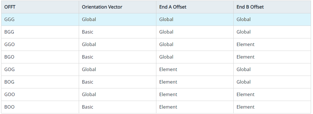
The offset components are stored at element level. This provides a provision to bulk update several elements without considering associated properties. Offset components are resolved based on OFFT string parameter.
Most of the offset tools described above will automatically apply offset values (End A & End B) in elemental system. Hence, OFFT will be automatically updated while using these tools (keeping the first letter unchanged for Orientation).
Setting the offset values directly using the Offset Component method honors the system option selected (Basic or Global).
For these solvers, the default position without offset is the Shear Center. Hence, using the Match with Shear Center option will set offset to (0,0,0).
The Match with Centroid option applies in elemental system an offset equal to the components of the beam section’s centroid from its shear center. This is typically used whenever the beam mesh was placed at the geometric center of the shape it represents.
If elements are CBAR, then both Shear Center and Centroid options leads to (0,0,0).
The element selector filters only elements which have a SECTION entity with card = BEAM. Other elements are not supported.
- If section entities are not used by others, the same entity will be updated.
- If section entities have other external references, a clone is made with the updated offset value.
Offset in section entity is understood in elemental system and only in-plane (Y/Z). The context does not expose an option for system or a way to apply offset along X (beam shortening).
- A positive offset along a direction moves the shape in the bottom direction.
- To be visually consistent, the same manipulator is displayed for incremental offset to apply opposite value.
- No extra logic is performed while entering direct offset components. Result is the same as updating the attribute in section entity.
- Applying an incremental offset :first convert string based offset to equivalent numerical value, so set resultant offset as user value.
- Using reference element.