JointLoad Method
The Rivet config is shipped with an internal method called JointLoad. This method determines the load transfer through bolted connections and the associated bypass and bearing loads in the adjoining plates. The JointLoad method extracts the internal loading in the plates and bolts of concern. The extracted data can either be:
- An ASCII text file (*.csv) written to disk at run
time.
- Files are subsequently parsed to feed an external static strength analysis.
- An option allows you to create *.csv files every N number of loadcases to reduce file size.
- Written inside tables in the HyperMesh session
and saved in a binary file.
- Tables can later be exported to an ASCII text file.
- Tables can also be used by subsequent chained methods running after JointLoad to assess margin of safety.
Fastener Modelization
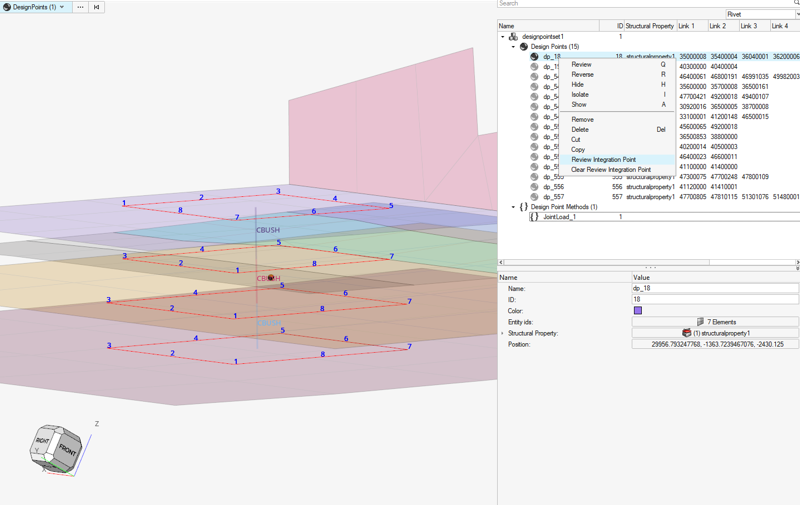
This method is tailored to run on designpoints of configuration Rivet. While generating a Rivet, the expectation is to have a collection of Pierced_shell-1D- Pierced_shell... that represent the fastener (Figure 1).
- Rutman modelization is not supported yet for force extraction.
- So called “Tension bolts” where each internal body between plates sustains shear only plus 1 element linking the top/bottom plates with tension stiffeness only are not supported in Fastener detection.
Force Extraction
Fastener Forces
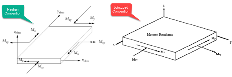
There are direct extractions of all 1D element forces Fx, Fy, Fz and bearing loads at the node interface between two 1D elements in case of multiple lap joints.
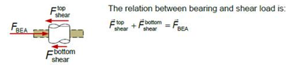
It should be noticed at this stage the difference between the fastener bearing load and the fastener shear load (Figure 2). For external plates, the shear and bearing load are equivalent because there is only one interface. For middle plates, the maximum absolute interface load is taken as the fastener shear load.
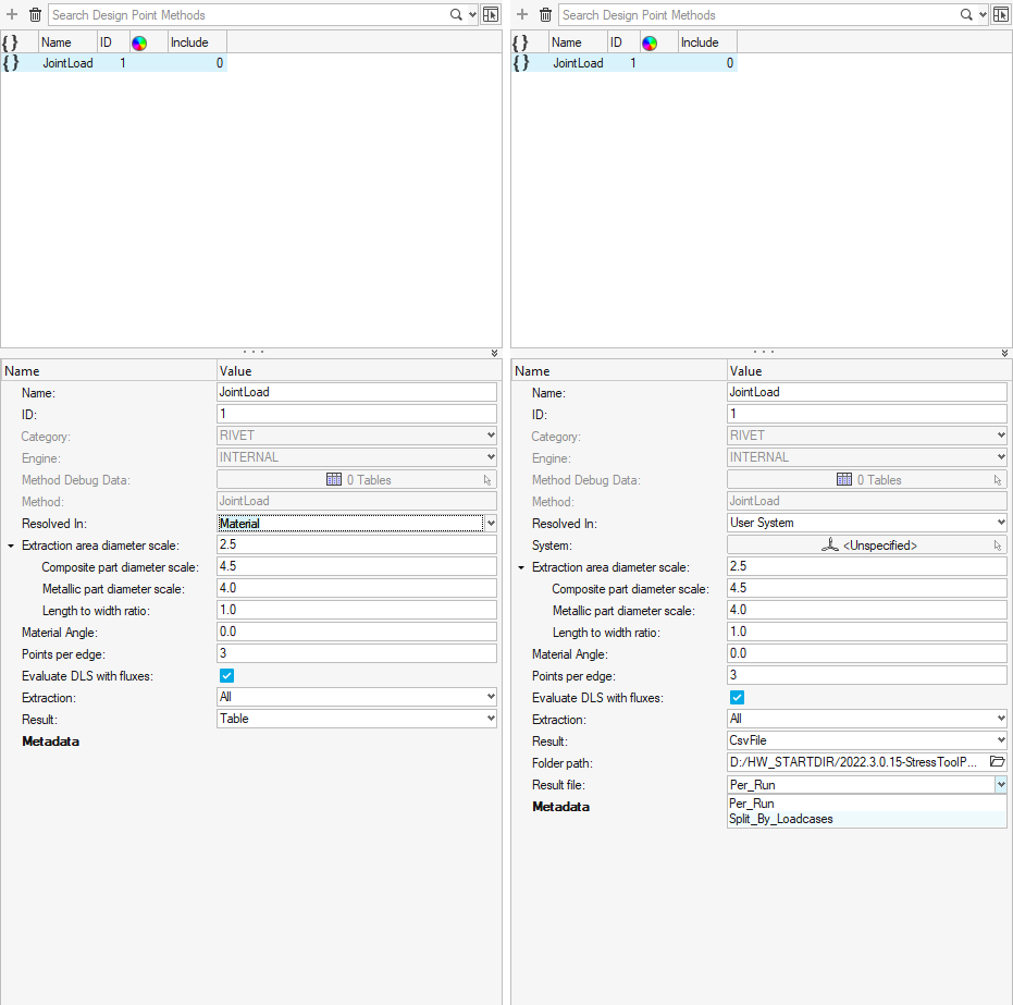
- Material (default)
- Elemental
- User system
If Elemental is selected, the pierced shell elemental X axis defines the local X axis.
If User system is selected, then the local X axis of the selected system is projected to the pierced shell to define the local X axis. If that projection fails (because X is colinear to shell normal) then elemental X is used instead.
The steps used to define Y,Z remain identical for all options.
The JointLoad method provides an input Material Angle (Figure 3) which allows you to rotate the system by a given angle around the shell normal. Shear force components of 1D elements are projected in that system.
It is worth noting that the material system used by the method is coming from the model in the current session, no matter which system was set in the Analysis run. Changing the MCID of a pierced shell in session will consider that system locally if extraction option is resolved in “Material”.
Whenever there is a lap joint, the contribution of 1D elements from both sides are properly summed.
Regarding the extraction of tension force, the pull-through force is rearranged by considering 1D direct element axial force (Fx) without projection. Output is reversed only if it is the output of 1D’s second node; otherwise the axial force is used directly.
The method outputs a value called MaxFz (max tension in fastener). This is the max value among calculated Fz, where 0 is returned if the bolt is in compression.
Shell Forces
- Extraction area diameter scale (def 2.5)
- Composite part diameter scale (def 4.5)
- Metallic part diameter scale (def 4.0)
- Length to width ratio (def 1.0)
Each fastener has a structural property assigned from which you can define a diameter. To calculate the box length from the fastener diameter and method level scale factors, the below formula is used:
Box Length=0.4*AreaScale*FastenerDiameter*Material_Diameterscale
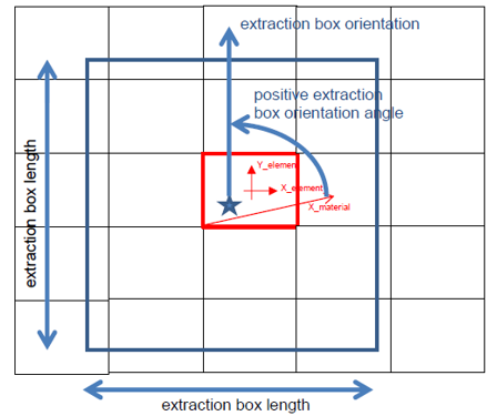
The length to width ratio applies on nominal Box length from the above formula and allows for a rectangular shape if the ratio is not 1.0.
The extraction box is aligned with a pierced shell's material system as described above; hence, the parameter Material Angle allows you to rotate the box from the X axis, calculated as per the Resolved-In option. The parameter Point per edges samples points per edge.
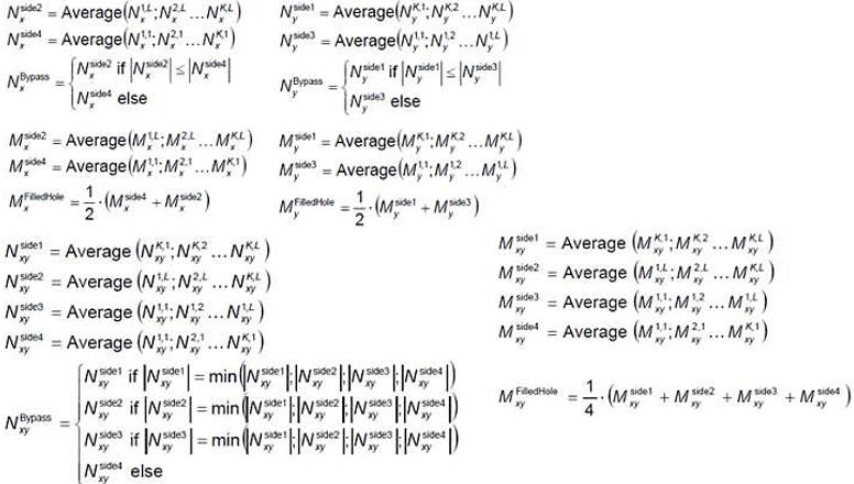
A field of shell forces/moments Nxx, Nyy, Nxy, Mx, My, Mxy is performed after averaging values from elements on nodes (considering corner data if available in the result file). A field query is performed in the material coordinate system on box edges on sampled points per edge. The number of integration points (points per edge) default to 3 but can be changed.
Force fluxes (resp. Moment fluxes) are evaluated per edge as an average of values on edge points (interpolated from the field at each point location). ByPass and Total fluxes are evaluated using the following equations:
Extraction is done per pierced shell of a Rivet designpoint.
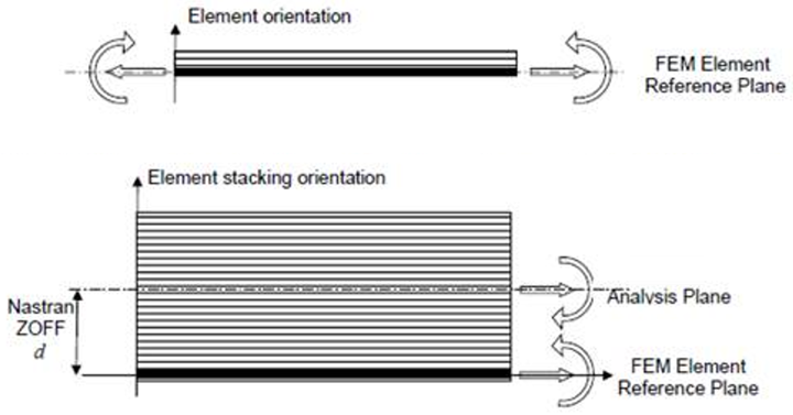
The tool also supports moment sign convention and correction in case of offsets (Figure 6 and Figure 7).
It extracts plate moments at the midplane. Nastran/OptiStruct element force results are given at the element reference plane and the reference plane coincides with the midplane even if element offsets (ZOFFS) are used. However, PCOMP Z0 != -t/2, this is no longer the case and moments must be corrected from the reference plane back to the midplane (Figure 7). This correction is done by the tool prior to producing the output. To consider moment correction if extraction is not performed at the middle surface, the following method is followed:
Output Options
DLS Ratio
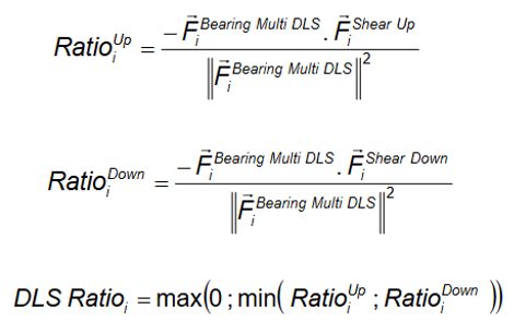
The method has a flag to evaluate DLS ratio (“true” by default) as seen in Figure 3. The DLS ratio is evaluated by the following procedure over each plate in the assembly:
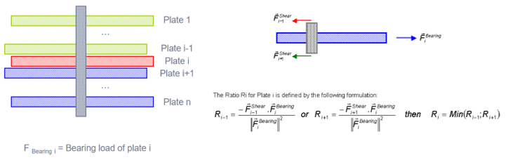
For a given plate, a ratio of the contribution of the Shear force over Bearing force from top/bottom elements is evaluated and the lowest is kept (Figure 8).
- Define Contribution for each plate Cik for plate
i
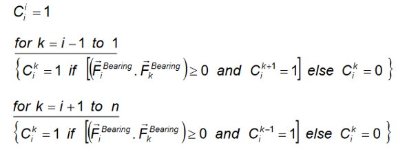
- Definition of Fbearing and Fshear for plate i
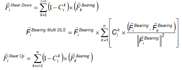
- Definition of DLS ratio for given plate i
Output Data and Format
Parameter Extraction (Figure 3) drives the output data written.
- Fastener Force
- Output per plate (elementid) the fastener forces and max tension (per loadcase).
-
Figure 9. Fastener Forces only 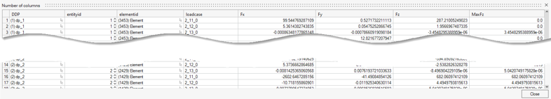
- Forces and Fluxes
- Output per plate (elementid) the fastener forces along with Bypass fluxes and DLS ratio. Running in this mode gives all necessary results while reducing memory footprint compared to All.
-
Figure 10. Forces and Fluxes 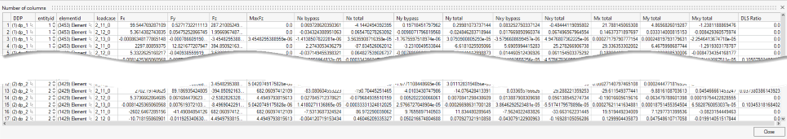
- All
- Output all debug information along with previous results. It includes the point coordinates where extractions happen as well as raw data extracted (Nxx, Nyy, ...) at these locations. It also provides all details of the connection (ID of 1D elements linked to a plate) and box dimension. This results in 85 columns being created. The column remark contains, in the first row, the extraction system being used.
-
Figure 11. All debug info 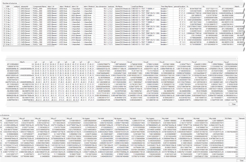
Another parameter – Result – drives how results are saved.
- Table (default)
- Creates a table entity in the HyperMesh
session, saved with the binary file.
- This is a mandatory option if a subsequent chained method aims to run after JointLoad.
- Csv File
- The run directly dumps result into a csv file on disk.
- It shows a folder location which defaults to the HyperMesh working directory.
- The file name is the same as the method name appended with RUN.
- The overwrite option has no impact here. The file name is always incremented if it already exists in the export directory.
- The generated csv file is comma-separated.
- Result file
- Available if Result is set to "Csv File".
- Loadcase size
- Available if Result File is set to "Split_ByLoadcases".
Prerequisites
JointLoad supports Nastran result formats as well as OptiStruct native *.h3d as result files.
- 1D element Forces
- 2D element Forces & Moments