First Ply Failure Method
The Panel_composite config comes with a set of various composite laminates first ply failure criteria. All of these failure criteria are bundled in a single certification method called “First_Ply_Failure”. This method internally invokes former ESAComp engine.
Despite the method being available under the Panel_composite config, it evaluates failure criteria per element basis. As mentioned before, if the structural property assigned to a given designpoint refers to a user-defined property (PCOMP or PCOMPG), then all attributes required by the method are queried from this property. Otherwise, it will go directly per element’s property. Details on the supported properties can be found in Solver Specific Details in Composite Stress Toolbox.
All composite stresses are recalculated from shell element forces and moments based on the reference laminate property used. It then requires that result files contain shell element resultant forces and moments.
Math
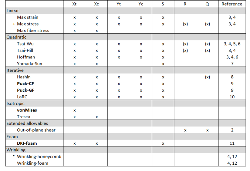
+ Max stress for isotropic material requires Xt, Xc, and S and considers out-of-plane shear.
- R= Transverse_Shear_Allowable_S13
- Q= Transverse_Shear_Allowable_S23
- *E3
The bold design criteria automatically consider out-of-plane shear stresses.
If R and Q (for MAT8) are defined, traditional in-plane criteria will also consider the out-of-plane shear.
| Failure Criterion | Parameter |
|---|---|
| Tsai-Wu | F12 (OptiStruct, Nastran), f* (Abaqus) |
| Puck-CF (carbon fiber) | Slope parameters: =0.35, =0.3, =0.275 Degradation parameters: s=0.5, M=0.5 |
| Puck-GF (glass fiber) | Slope parameters: =0.30, =0.25, =0.2225 Degradation parameters: s=0.5, M=0.5 |
| LaRC | alpha=53° |
Terminology
Failure Index is the value of the failure function at the given load.
Reserve Factor/Factor of Safety is a measure of margin to the onset of failure. The effective load multiplied with the Reserve Factor gives the design margin. Thus, Reserve Factor values greater than one indicate a positive design margin and values less than one indicate a negative design margin. The values of Reserve Factors are always greater than zero.
Inverse Reserve factor = 1 / Reserve Factor
For linear criteria (max strain, max stress and max fiber stress), it is equal to the value of the failure function f. For other failure criteria, there are either closed form solutions or iterative procedures to calculate the Reserve Factor from the Failure Index and the Inverse Reserve Factor, respectively. If the load factor has been increased by 2e32 in iterative solving or the Failure Index is below 1e-32, then the Inverse Reserve Factor is set to 0, which corresponds to reserve factor being infinite.
Margin of Safety = Reserve Factor – 1.
As opposed to the Factor of Safety as the margin to be reported, you can also use safety factors to adjust the effective load used in the margin calculation while accounting for influences of statistical load distributions, allowables, or other design aspects. Two options are exposed in the First Ply Failure method.
Design Safety Factor is multiplied with the applied load Fapplied to get the effective load Feff.
Feff = Design Safety Factor * Fapplied
Stability Factor is used in addition to Design Safety Factor to account for the fact that many stability problems are modeled based on ideal structures while they are not geometrically perfect in reality. Hence, for stability related analyses (for example, wrinkling):
Feff = Stability Factor * Design Safety Factor * Fapplied
Both factors are utilized in load response failure and strength analysis. For strength analysis, this means that the critical loads shown are the applied loads that lead to onset of failure with given safety factors in effect.
Activate Failure Theories
Once the First_Ply_Failure method is added to a designpointset, you can edit it from the browser. First, you can select the result level (Element | Layer | Recovery plane), then the type of margin to evaluate.
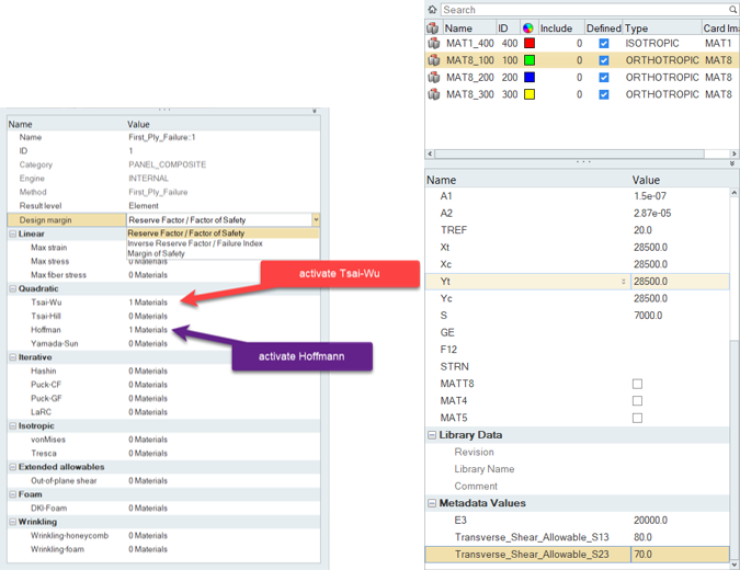
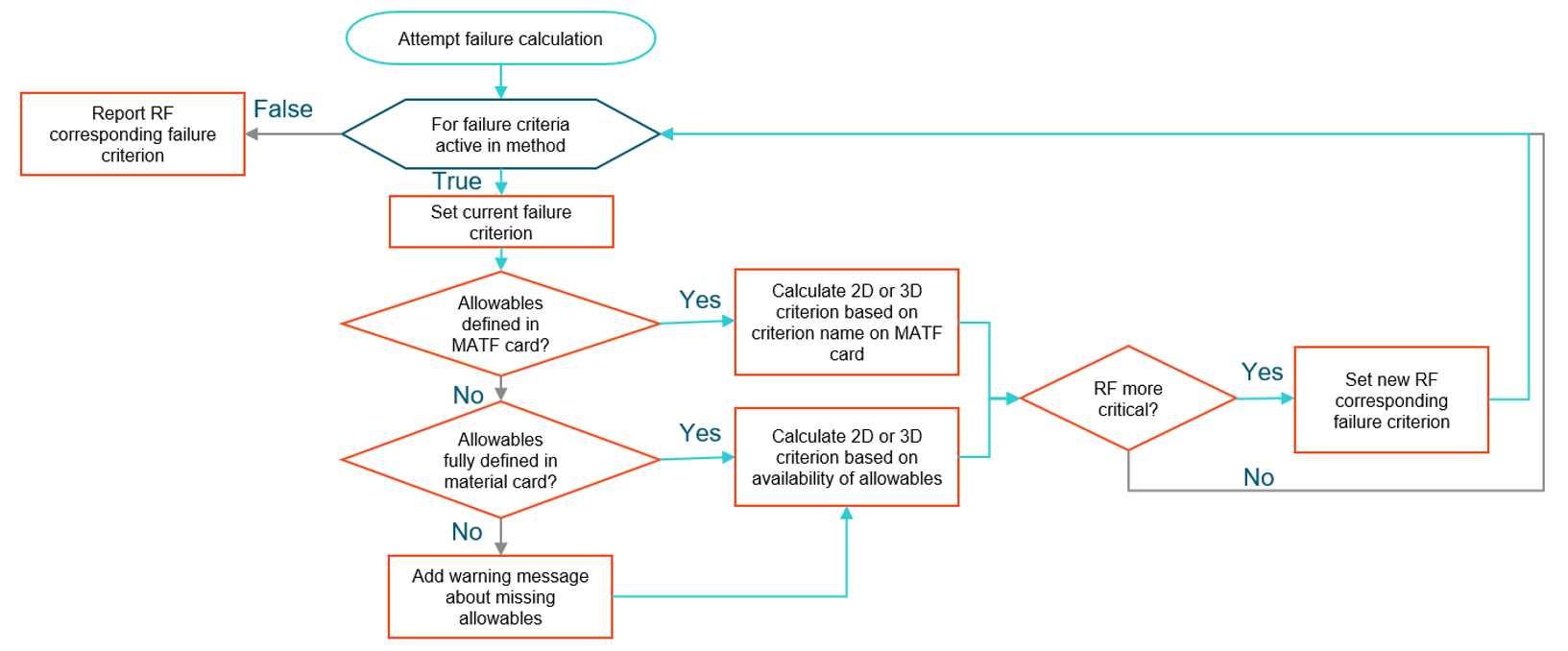
Multiple selections and combinations of failure criteria requiring different allowables are supported. The logic is outlined in Figure 3.
- 2D: PUCK, HILL, HOFF, TSAI, HASH, STRN, STRS
- 3D: PUCK3D, HILL3D, HOFF3D, TSAI3D, HASH3D, STRN3D, STRS3D
- MATF PUCK3D, TSAI3D, and HASH3 failure criteria supports reading the allowables only, but not the additional parameters (W1, W2, W3). Standard set for those parameters for glass fiber and carbon fiber is used as per the ESAComp documentation for PUCK. F12 is used for TSAI3D. W1=alpha=1 is used for HASH3D.
Example 1: Local Post-Processing
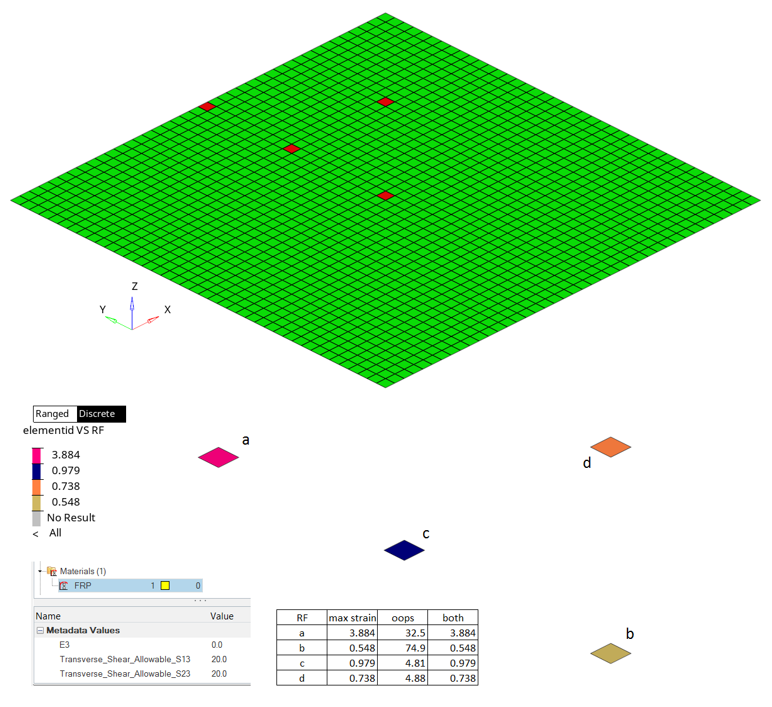
Example 2: Global Post-Processing
First Ply Method References
- Mechanics of Composite Materials, Jones, R.M., Hemisphere, New York, 1975.
- Improved transverse shear stresses in composite finite elements based on first order shear deformation theory, R. Rolfes, K. Rohwer, International Journal for Numerical Methods in Engineering, 40:51–60, 1997.
- Failure criteria for an individual layer of a fiber reinforced composite laminate under in-plane loading. ESDU 83014, Amendment A. Engineering Sciences Data Unit, London, 1983/1986.
- Structural Materials Handbook, Volume 1 - Polymer Composites. ESA PSS-03-203, Issue 1. ESA Publications Division, ESTEC, Noordwijk, 1994.
- Introduction to Composite Materials. Technomic, Tsai, S.W. and Hahn, H.T., Westport, CT, 1980.
- Theory of Composite Design, Think Composites, Tsai, S.W., Dayton, OH, 1992.
- A Study of Failure Criteria of Fibrous Composite Materials, Paris F., George Washington University, Langley Research Center, Hampton, Virginia, NASA/CR-2001-210661.
- Failure Criteria for Unidirectional Fiber Composites, Hashin, Z., Journal of Applied Mechanics, 47 (1980), pp. 329-334.
- Failure criteria for non-metallic materials, Implementation of Puck´s failure criterion in ESAComp, FAIL-HPS-TN-003, European Agency Contract Report No. 16162/02/NL/CP, Braunschweig, 2004.
- Progressive failure analysis of advanced composites, Camanho P., NASA FA8655-06-1-3072, June 2009.
- Advanced Material Models for the Creep Behaviour of Polymer Hard Foams; Latest Advancements of Applied Composite Technology, Roth, M. A., Kraatz, A., Moneke, M., Kolupaev, V., Proceedings 2006 of the SAMPE Europe, 27th International Conference, Paris EXPO, Porte de Versailles, Paris, France, 27th - 29th March 2006. ISBN 3-99522677-2-4. pp. 253 - 2258.
- Manual for Structural Stability Analysis of Sandwich Plates and Shells, Sullins, R.T. et al, NASA CR-1457. 1969.
- A higher-order plate element for accurate prediction of interlaminar stresses in laminated composite plates, Ramesh S.S., Wang C.M., Reddy J.N. and Ang K.K., Composite Structures 91 (2009) 337–357.