Author Custom Methods
Register new methods and save/import existing libraries. Method Manager shows these steps in more detail.
Method Entity Structure
To understand the required steps, you should be familiar with the structure of methods and libraries.
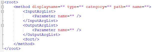
It requires a main block <root> which contains a list of
<method> tags.
You can optionally add attribute name=”user library name” at the
<root> level. The user name displays in the Method
Manager.
It requires a main block <root> which contains a list of
<method> tags.
A method is:
- A reference to a function, such as retval=myfunc(x,y,z), defined in an external file (Compose, Python, Tcl, DLL)
- The ordered list of input arguments mapping
- The ordered list of output argument names
- Optionally, a post evaluation sorting (aggregation)
Method Attributes
The method tag, in xml, requires some mandatory attributes, see Figure 1.
- displayname=" "
- The name displayed in the Method Manager dialog. It serves as an identifier key.
- When a designpointmethod entity is created in the HyperMesh database, it comes with an ID, a name
(HyperMesh entity name) and an attribute
Method which will be set to the value of
displayname from the .xml file.
Figure 2. Method Entity Editor 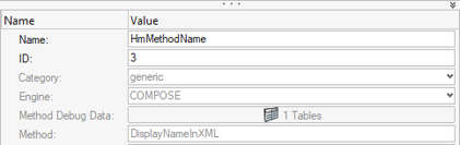
- type="DLL | PYTHON | COMPOSE | TCL"
- The engine used to run the method. It is saved as dataname “Engine” in a HyperMesh designpointmethod entity (Figure 2).
- path=" "
- The file path of the Python/Compose/Tcl file where functions are defined. It can be either an absolute path or a relative path from the library file path.
- name=" "
- The true function name as defined in the Compose/Python/Tcl file.
- category="Rivet | Spring | Panel_metallic | Panel_composite | Generic"
- Used to filter the list of available methods in the UI. Category value is on par with designpointset config.
- corner= ”true |false” (def false)
- resavg=”none |simple |min |max |ext | sum” (def: none)
- hideoption=”true |false”
- Can be used to set the default for corner and resavg, but disables you from changing them.
Then, two tags are mandatory to specify the input parameters and method outputs:
- InputArgList
- Defines mapping between method inputs and model/result/user keys to query from the engines. The list of parameters must be ordered in the same way as the method arguments.
- Dynamic data names are added to designpointmethod (resp
structuralproperty) along with regular data names that come with the
selected config. These are not metadata anymore. In the following
example, a string condition was added (called condition) to a
designpointmethod. It accepts two values:
- Condition1
- Condition2
Figure 3. 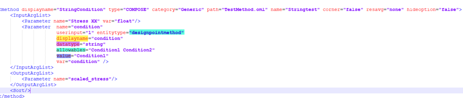
- When created from this template, the method is shown as:
Figure 4. 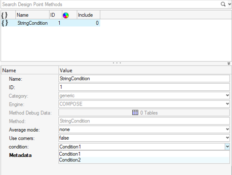
- Metadata values
- When the engine runs a method with definition that uses user input parameters, it expects that the data exists at run-time. The engine always uses values defined at the entity level in the database no matter the value set in xml.
- OutputArgList
- Methods can output multiple (pre-defined) results.
- Whenever multiple methods are assigned to the same location, an extra
consolidated table is created considering all methods having one
attribute with marginofsafety="1". Then, methods
are compared against each other using as a metric the parameter tagged
as marginofsafety.
Figure 5. Method table: Input & Output 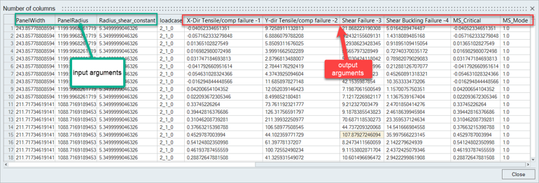
Sorting
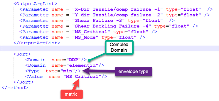
Inside method registration, it is possible to add a Sort block. As a result, the method will still be evaluated for each entity inside a designpoint (element | layer) as well as each loadcase.
However, after method run, an aggregation is performed on a Domain using a metric and envelope type. The result of this aggregation is that table output by method will retain only aggregated values. The envelope type can be spatial and/or on loadcases depending on the domain (Figure 6).
- Type (of envelope)
- Valid types are:
- Min
- Max
- AbsMin
- AbsMax
- Value
- The value can be any float parameter either from InputArgList or OutputArgList. It is used as comparison metric.
- Domain
- Domain can be a combination of multiple keys in the following list:
- DDP
- entityid
- elementid
- nodeids
- layerindex
- loadcase
- DDP |entityid |elementid|layerindex |nodeids: Performs a loadcase envelop. If corners or nodal data was considered, they are kept after sorting.
- DDP |entityid |elementid|layerindex: Performs a loadcase envelop. If corners or nodal data was considered, they are aggregated.
- DDP |entityid |elementid|nodeids|loadcase: Performs aggregation across the element’s layers. Keep result per loadcase.
- DDP |entityid |elementid: Performs loadcase envelope. Spatial aggregation to retain critical value per element.
- DDP | entityid: Performs loadcase envelope. Spatial aggregation to retain critical entity (panel or freebody).
- DDP |nodeids |loadcase: Aggregate value on nodes of a given DDP (keep DDP boundaries). Per loadcase.
- Whenever there are critical values across loadcases, contour is available only for envelope loadcases and no more load case per load case.
- Whenever results across layers are aggregated, contour is available only at the element level.
- Whenever an aggregation is done across elements (on a designpoint) the table will have the following: DDP | elementid | loadcase | ..inputs | ..outputs | metric, where metric uses critical values. As a result, only one element ID is kept per designpoint in the table. However, the contour method feature has the ability to select DDP as an entity, which contours a constant value on all elements inside the structural element.
Input Aggregation
<Parameter name = "Composite Stress XX"
                perlayer="0"
                sort=”min|max|minmax|sum|avg|absmin|absmax” (optional)
/>
This way, all layers are queried for Sxx before calling a method, and only the min or max will be retained and sent to method. In the case of minmax, both the min and max values are sent as a vector to method. The sort key is optional. If sort is not requested, all layer values of Sxx will be sent at one time (as a vector) to the method.
- perlayer="0|1"
- 0 means list of all layers (method is called per element only)
- 1 (def) means current layer only (method is called per layer)
- perelement="0|1"
- 0 means list of all elements (method is called per designpoint only)
- 1 (def) means current element only (method is called per element)
- perloadcase="0|1"
- 0 means list of all loadcases (method is called once for all loadcases)
- 1 (def) method is called per loadcase
User Attribute Registration
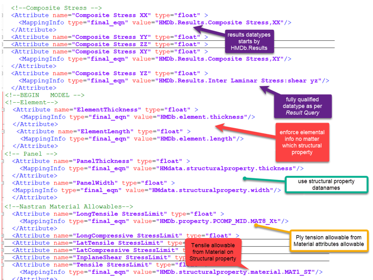
Registered attributes are either Model info queried from the HyperMesh database or Result info queried from result files. Result datatypes must match names in the result file. Most of the time, the result reader provides aggregated vector or tensor datatypes.
- 1DForces & 1DMoments
- 2DForces & 2DMoments
- Stress
- Composite Stress
- HMDb.property.PCOMP_MID.MAT8_Xt queries the ply’s material Xt (Nastran solver attribute) based on the order of precedence mentioned above.
- HMDb.element.property.PCOMP_MID.MAT8_Xt will always go with the local element’s property no matter which property is assigned (or not) to the structural property.
- HMDb.element.thickness will retrieve elemental thickness in a Panel (metallic & Composite).
- HMDb.structuralproperty.thickness enforce to use attribute thickness for Panel_metallic structural property.
If an attribute can take multiple values on an element (like material allowable per ply), the engine will manage during the query loop layer per layer.
- Re-defining an attribute with the same name as in the installation takes precedence in methods in the same library.
- Attributes with the same names across libraries are resolved locally.