Building a Two-Wheeler Model with an Aerodynamic System
In MotionView, models are assembled from libraries of pre-defined systems using the Assembly Wizard. The Assembly Wizard dialog guides you through the assembly process, ensuring that your selections are compatible.
Note: The MBD Vehicle Dynamics Tools preference files must be loaded before using the event
builder. Select from the MotionView interface.
- Starting the Assembly Wizard.
-
- In a MotionView session, click and select Two wheeler as the Wizard
Library.
Figure 1. 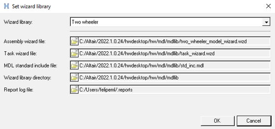
- Click .
The Two wheeler - Model Type dialog opens.
- Select the Full motorcycle with driver option and click
Next.
Figure 2. 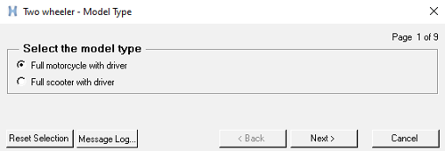
- Select the Aerodynamic Forces in the additional systems
tab and complete the model selection.
Figure 3. 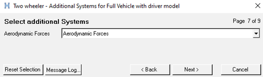
- The Full vehicle with driver model including the aerodynamic forces system build
through the Assembly Wizard is displayed in the graphics area.
Figure 4. 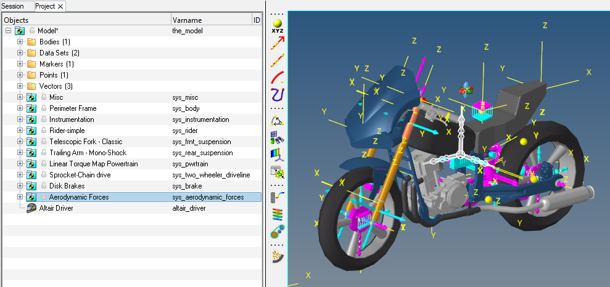
- Click on the Aerodynamic Forces system to display the
Attachments section in the panel area.
Figure 5. 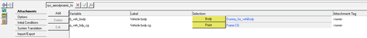
Attachments Description Vehicle Body (Body) Vehicle body where the action forces of the Aerodynamic system is applied. Vehicle Body CG (Point) Center of gravity point of the vehicle. - Under Data Sets, the aerodynamic property file is defined.
Figure 6. 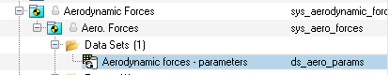
Figure 7. 
- The Center of pressure point (p_center_of_pressure),
where the aerodynamic forces are applied, is by default parametrized with the
Center of Gravity of the vehicle using the Attachment Vehicle Body CG
(Point) (p_veh_bdy_cg). By either entering the center pressure point
in the Attachment or modifying the coordinates of the Center of
Pressure point it is possible to specify the location of the
aerodynamic force applications.
Figure 8. 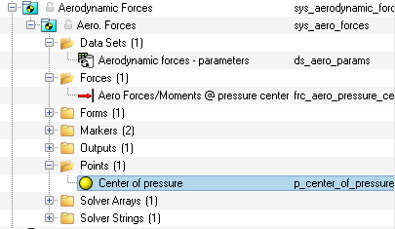
- In a MotionView session, click and select Two wheeler as the Wizard
Library.