Lines
Use the tool to create curve graphics from a set of selected points or nodes. The generated curve graphics can be used to setup 2D rigid to rigid contact or advanced joints, such as point to curve or curve to curve joints. Based on the selected set of points or nodes belonging to a file graphic or CAD graphic, this tool creates a 3D cartesian curve and a curve graphic.
Create Curve From Points/Nodes/Edges/Faces
The Create Curve From Points/Nodes/Edges/Faces macro allows you to create curve graphics from a set of selected points or nodes, or extract a curve from an edge/face of a geometry represented through CADGraphics.
Create Curve From Points/Nodes
Use the Points/Nodes option in the drop-down menu to create a curve graphic using points or nodes.

| Option | Description |
|---|---|
| System | Use the System collector to select the system in which you want to place the curve graphics. |
| Body | Use the Body collector to select the body with which the curve graphics will be associated. |
| Labels | Allows you to input the prefix for curve and the curve graphics that will be automatically created. |
| Open/Closed curve | Allows you to leave the ends of curve open OR generate a closed curve by automatically joining the first and the last point/node. |
| Point/Node | Use the Point/Node collector to select the points/nodes that
will be used to generate the curve. Use the Remove button to remove single/multiple selections of points/nodes from the panel list. The All |
| Create | Use the Create button to run this macro and create the curve and the graphics once you are done selecting the points/nodes and providing other details related to the curve. |
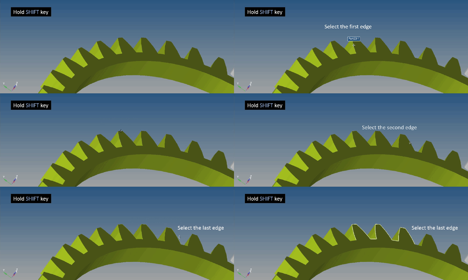
Create Curve from Edges/Faces


Create Lines
-
From the Model ribbon, Geometry tool set, click the Lines
tool.
The Lines panel is displayed.
-
Click the System collector to identify the system or
container into which the curve graphics will be created.
The Model label means that the graphics will be created in the main model.
- Click the Body collector and select a body from the modeling window, or double click the Body collector to open the Model Tree (from which the desired body can be selected).
- Specify a label for the curve and the curve graphics that will be automatically created.
- Use the drop-down menu to leave the ends of the curve open or generate a closed curve by automatically joining the first and last point/node.
- Click the Point/Node collector and choose points and nodes from the modeling windowor the Model Tree.
-
Highlight the points or nodes that will make up the curve.
Tip:
- To select all the points/nodes, click Select
All
 .
. - To deselect all points/nodes, click Select
None

- You can also reverse the selection status of the components in the
list by clicking Reverse Selection
 .
.
- To select all the points/nodes, click Select
All
- Click Create to create the curve and the graphics.