Vectors
Use the Vectors tool to create and edit vectors.
Vectors are entities that can be used for orienting other entities such as joints, bushings, beams, coil springs, etc. Vectors provide direction and have no particular location in space.
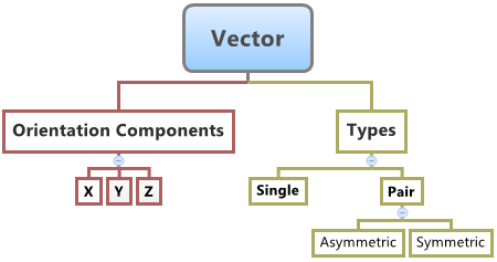
You can create single vectors and pair vectors (asymmetric or symmetric) in MotionView.
When used to orient entities in MotionView, the corresponding axis of the markers of the entity (the primary axis that defines the entity direction) gets oriented in the same direction as that of the vector. For example, when a vector is used to orient the direction of the revolute joint, the Z axis of the joint I and J markers are oriented along the direction of the vector.
Create Vectors
- From the Browser, select the system to which the vector entity is to be added.
-
From the Geometry ribbon, click the Vectors tool.
A guide bar for entity creation appears.
- Optional:
Select the Pair check box to create a pair entity.
A vector entity, like most of the entities that are created in MotionView, can be a single entity or a pair entity. Pair entities help to create models that are symmetric about the Z-X plane of the model. Their properties can also be symmetric about the Z-X plane (in other words, the Y property is mirrored). Asymmetry or symmetry of the vectors can be decided or specified when editing the created vector.
-
Select a point origin reference (Origin 0).
- Select a point in the modeling window.
OR
- On the guide bar, click the Advanced
Selector
 and make your selection in the Model Tree.
- Select a point in the modeling window.
- Optional:
Click
 to reset the entity selections and select new
entities.
to reset the entity selections and select new
entities.
-
Once the reference selections are made, create the vector using one of the
following methods:
- Click
 on the guide bar to create and orient the entity.
Next, use the microdialog to edit/orient the
vector.
on the guide bar to create and orient the entity.
Next, use the microdialog to edit/orient the
vector. - Click the
 button that appears at the mouse location in
the modeling window. Next, use the microdialog to
edit/orient the vector.
button that appears at the mouse location in
the modeling window. Next, use the microdialog to
edit/orient the vector. - Click
 to create the entity and exit the guide bar selections for this vector.
Once the vector has been added to the model, the corresponding vector will automatically be displayed in the browser area.Note: By default, variables names of entities in MotionView follow a certain convention. For example, all vector entities have a variable name starting with 'v'. This is the recommended convention to follow when building models in since it has many advantages in model editing and model manipulation. - Click
Edit Vectors
-
If the Vector panel is not currently displayed, select the desired vector by
clicking on it in the Model Browser or in the modeling window.
The Vectors panel is automatically displayed.
-
Enter a value for the X, Y, and Z components in the Properties tab.
Note: If the selected vector is a pair entity, first distinguish between the Left and Right tabs in the panel, and then edit the properties. Checking Symmetric properties will prompt a dialog where you can make the values symmetric with respect to either side.