Markers
Use the Markers tool to create coordinate systems and reference frames.
A marker entity is an orthonormal, right-handed coordinate system and reference frame in MotionView. Marker is a primary entity in a multibody system and is used in the solver to represent all entities that make up a multibody system.
A marker must belong to a body. The body can be of any type: rigid, flexible, or point mass.
Create Markers 
- Parent Body
- Origin Point
- Orientation
Use the Markers tool set in the Geometry ribbon to create markers in the following ways:
- From the Browser, select the system to which the marker entity is to be added.
-
From the Geometry
ribbon, click the Markers tool set
to invoke the Markers create/edit context.
A Markers guide bar appears (the Body collector is active by default).
- Optional:
Select the Create Pair check box to create a pair
entity.
A marker entity, like most of the entities that are created in MotionView, can be a single entity or a pair entity. Pair entities help to create models that are symmetric about the Z-X plane of the model. Their properties can also be symmetric about the Z-X plane (in other words, the Y property is mirrored). Asymmetry or symmetry of the markers can be decided or specified when editing the created marker.
-
Resolve the Body collector either by clicking on a body
graphic in the modeling window or using the Advanced
selector
 .
The selected body is highlighted in red.
.
The selected body is highlighted in red. -
Resolve Origin using one of the following methods:
- Click on an existing point in the modeling window.
- Hover and click on a CADGraphic location – an edge corner, center or surface center. A new Point will be created at this location.
- Use the Alt key to highlight the mesh of CADGraphic or FileGraphic. Hover and click on a node. A new Point will be created at this location.
- Use the Advanced selector to pick an existing point.
A microdialog with a Create button is now displayed since all the required references have been resolved. - Click the Create button on the microdialog to create the marker.
-
Click on the Orient Marker icon
 on the microdialog in the
modeling window to change the orientation using the
Orientation tool.
on the microdialog in the
modeling window to change the orientation using the
Orientation tool.
Edit Markers
-
Edit using the Markers tool:
-
To edit the Body to which the marker belongs:
- Click on the Body collector and pick
another body from the modeling window or
use the Advanced Selector icon
 (next to the collector) and pick
the body from the list that appears in the dialog.
(next to the collector) and pick
the body from the list that appears in the dialog.
- Click on the Body collector and pick
another body from the modeling window or
use the Advanced Selector icon
-
To edit the Origin of the marker:
- Click on the Origin collector and pick
another point from the modeling window
or use the Advanced Selector icon (next to the collector) and pick
the body from the list that appears in the dialog.
- Click on the Origin collector and pick
another point from the modeling window
or use the Advanced Selector icon
-
Click on the Orient Marker icon on the microdialog
in the modeling window to change the orientation
using the Orientation tool.
-
To edit the Body to which the marker belongs:
-
Using the Entity Editor:
- Select the marker that needs to be edited. Its properties are listed in the Entity Editor.
-
Activate the Body or Origin collector and pick another body or point
from the graphic screen respectively or click on the icon next to the collectors to use the
Advanced Selectors.
- To change the orientation, use the Orientation section.
Property Description General Label Descriptive label for the entity. Varname Variable name of the entity. ID Integer identifier. Active Active state of the entity (True or False). Entity is deactivated if False. Body Parent body that the marker belongs to. Origin Point of origin of the marker. Orientation Orientation Method Method of orientation. The following choices are available: 2-Axes Orient marker using the “Axis-Plane” method. Provide a direction for an axis and another direction that lies in a plane defined by the 1st axis and 2nd Axis. 1st Axis Direction Select a direction – X | Y | Z axis. Align method Select a method for aligning the chosen axis along a direction – Point | Vector | DxDyDz. If Point is chosen, pick a point in the modeling window or through the Advanced selector . If Vector is chosen, pick a vector through the modeling window or through Advanced Selector
.If DxDyDz is chosen, enter the direction cosine values.
2nd Axis Direction Select a plane. The available choice depends on the 1st Axis. For example if Z-Axis is chosen, the available choices are the ZX | ZY planes. Align method Select a method for aligning the chosen plane – Point | Vector | DxDyDz. If Point is chosen, pick a point in the modeling window or through the Advanced selector .If Vector is chosen, pick a vector through the modeling window or through Advanced Selector
.If DxDyDz is chosen, enter the direction cosine values.
1-Axis Orient marker using the 1-Axis method. Provide a direction for an axis. MotionView will orient the other axes automatically. This option can be used when only one axis direction is of importance. 1st Axis Direction Select a direction – X | Y | Z axis. Align method Select a method for aligning the chosen axis along a direction – Point | Vector | DxDyDz. If Point is chosen, pick a point in the modeling window or through the Advanced selector .If Vector is chosen, pick a vector through the modeling window or through Advanced Selector
.If DxDyDz is chosen, enter the direction cosine values.
Angles Orient marker using the euler angles. Provide three sequential rotations about Z-X’-Z” axes. Where X’ is the new X after the first rotation (about the Z axis) and Z” is the newly oriented Z axis after the first two rotations. Z Rotation in degrees about the Z axis with respect to the Ref Marker. X’ Rotation in degrees about the new X axis after the first rotation about Z. Z” Rotation in degrees about the new Z axis after the second rotation about X’. Ref Marker Reference marker about which the marker is oriented. DC Display the direction cosine matrix. The DC matrix shows the unit vector direction of each of the axes of the marker. Appearance Visible Controls the visibility of the entity on the modeling window. Note & Tags Note Optional descriptive note. Attachment Candidates Add tags for the entity as possible attachments to Systems/Assemblies/Analyses.
Orientation
Use the Orientation tool to align an entity along a particular direction.
- Vectors
- Joints
- Bushings
- Markers
- Gears
- Vector Orientation
- This tool orients one axis or a vector. This tool is used to orient the
following entities:
- Vectors
- Non-compliant Joints
When in the edit context of an entity listed above, click on the Orientation tool. The VectorOrientation tool appears.Figure 1. 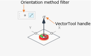
The tool is made up of a vector arrow indicating the direction and a plane orthogonal to the vector direction. The arrow tip has a circular handle. The tool is also accompanied with a microdialog containing a Point and a Vector icon to use as a filter for the method of orientation.
- Marker Orientation
- This tool orients a reference frame by the Axis-Plane method and is used
to orient:
- Markers
- Bushings and Compliant Joints
When in the edit context of entity listed above, click on the Orientation tool. The Marker Orientation tool appears.Figure 2. 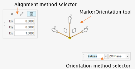
The tool is made up of three directional vectors and two microdialogs:- The Orientation method selector to choose the Axes and Plane.
- A Filter for the method of orientation (containing a Point, Vector, and Direction Cosines icon).
- To orient:
- Select 1-Axis or
2-Axes in the Orientation method
selector.
- 1-Axis orients the entity using only one axis. The remaining axes are oriented automatically.
- 2-Axes orients the entity which requires information for two axes.
- Click on one direction vector (X,
Y , or Z) to
select the primary axis of orientation.
- If 2-Axes is selected, the planes associated with the selected vector gets displayed in the tool as well as listed in the Axes-Plane selector.
- Use the Alignment method filter to align
the axis either along a point, a vector, or use the direction
cosine.
- Hold the handle at the vector end, rotate around.
- Hover over a Point (a Point entity of CAD vertex) or a Vector based on the orientation method chosen on the filter.
- Once the desired aligning entity is highlighted, release the mouse to select the highlighted entity. The axis will be aligned along the selected direction.
- If 2-Axes is selected, click on the Plane handle. The handle is
selected.
- Hover and click over a Point (a Point entity of CAD vertex) or a Vector (a Vector entity or CAD edge) based on the orientation method chosen on the filter.
- The second axis will be aligned such that, the selected reference lies in the plane formed by the two axes of the entity.
Figure 3. Depiction of the XZ plane of the Marker containing Point 2 used for orientation 
- Select 1-Axis or
2-Axes in the Orientation method
selector.