Advanced Meshing Options
A number of advanced meshing options are available that allows you the flexibility and advanced mesh control for segments, triangles, tetrahedra and voxels.
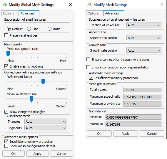
Suppression of Small Geometry Features
- Default
- The mesh created with this option will not mesh (mesh over) very fine
geometric details. To include very fine geometric details in the mesh,
select the Preserve all entities check box.
- Preserve all entities
- This option is used to retain all the edges after meshing. This means that tiny edges will be preserved and will not get collapsed.
- Size
- This option creates a mesh with a specified minimum element size. If the geometry detail is smaller than this limit, the mesher will ignore this detail.
- Ratio
- This option creates a mesh where the ratio of the maximum element to the minimum element conforms to the specified ratio.
- Fraction of voxel size (0,1)
-
This option limits how small voxels are allowed to become compared to their ideal size, where ideal size refers to the size determined by electromagnetic properties or the specified value. The position of gridlines is influenced by points of interests on the geometry. Points of interest that are closely spaced will result in unnecessarily small voxels.
Select Manual setting to specify a value between 0 and 1, where the value 1 relates to the ideal voxel size.
Mesh Quality
- Mesh size growth rate
- This option controls how quickly the mesh size changes. Fast allows an abrupt jump from small to large elements, while for Slow, each adjacent triangle will increase in size with less than twice the size of its previous neighbour.
Curved Geometry Approximation
These options control how curved geometry is approximated when creating the mesh.
- Refinement factor
- This option controls how fast the mesh will refine when it determines that the mesh does not adequately conform to the model. Fine allows smaller triangles to be used for small details but will increase the time to mesh the model.
- Minimum element size
- This option limits the size of the small triangles that are used to conform to the geometry, relative to the requested mesh size on that part.
- Allow elongated triangles
- This option allows the use of long, thin triangles and can lead to a
reduction in the number of mesh elements (depending on the geometry that is meshed).
- Aspect ratio
- This option limits the ratio between the length of the longest edge of a triangular mesh element height of the element (where height is defined as the perpendicular distance between the point of the triangle which is not on the longest edge and a line passing through the points on the longest edge). The aspect ratio is only applicable to curved surfaces and is limited by other mesh settings - such as the growth rate.
Curvilinear Mesh
- Curvilinear Mesh Triangles
-
- Auto
- This option allows the curvilinear mesh triangles to be used if curvilinear mesh triangles are likely to result in a more efficient solution using less memory.
- Disabled
- This option creates flat triangular elements.
- Enabled
- This option creates curvilinear mesh triangles (if supported by the solution method).
Note: HOBF must be enabled for curvilinear meshing (except for windscreen reference elements and when using the RL-GO solution method).Figure 2. A model with flat triangular mesh (on the left) and with curvilinear mesh and higher order basis functions enabled (to the right). 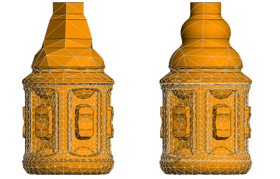
- Curvilinear Mesh Segments
-
A curvilinear mesh segment is created using second order segments with three vertices.
- Auto
- This option allows the curvilinear mesh segments to be used if curvilinear mesh segments will result in a more accurate solution with the selected solution method.
- Disabled
- This option creates straight mesh segments.
- Enabled
- This option creates curvilinear mesh segments (if supported by the solver method).
Figure 3. A helical wire meshed with straight segments (on the left) and with curvilinear mesh segments (to the right). 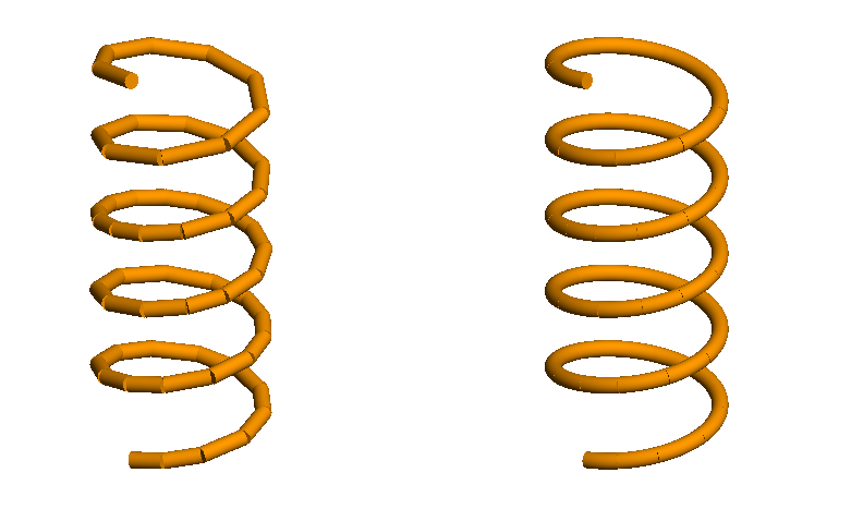
Note: Curvilinear mesh segments not supported for windscreen solution elements.
Aspect Ratio
This option controls the ratio between the longest and shortest side lengths of a voxel. Specifying the aspect ratio adds additional grid lines to decrease the side with the greatest length.
- the value 1 relates to voxels with equal side lengths.
- the value 100 relates to a 100:1 aspect ratio.
Growth Rate
The option limits the changes in size between adjacent voxels.
Ensure Connectivity Through Wire Tracing
This option allows a thin face to be replaced by a wire to ensure connectivity in a voxel mesh.
Select the Ensure connectivity through wire tracing check box to replace a thin PEC face with a wire. The intrinsic wire radius is determined by the Solver.
When this option is not selected, sections of the model that should be electrically connected might not be connected in the voxel representation.
Ensure Continuous Region Representation
This option allows a thin dielectric region (with a thickness smaller than the voxel size) be represented in the voxel mesh.
When this option is not selected, thin dielectric regions will not be represented in the voxel mesh.
Insufficient Memory Protection
This option prevents a large model to mesh if there is not sufficient memory available. Clear the Insufficient memory protection check box to disable this feature.
Show Mesh Configuration Details
This option when selected shows the calculated meshing parameter values such as Grade factor, Minimum to maximum size ratio, Maximum angle per element, Curvature minimum element size and aspect ratio.