Modifying the Mesh Settings
Discretisise the model into segments, triangles and tetrahedra (where applicable) or modify the mesh settings.
Note:
- To generate a tetrahedral mesh, activate the FEM solution method.
- To generate a voxel mesh, activate the FDTD solution method.
-
Open the Create Mesh dialog using one of the
following workflows:
- On the Mesh tab, in the
Meshing group, click the
 Create Mesh icon.
 - Press Ctrl+M to use the keyboard shortcut.
Figure 1. The Create Mesh dialog (Options tab). On the left, the dialog for triangles and to the right, the dialog for voxels. 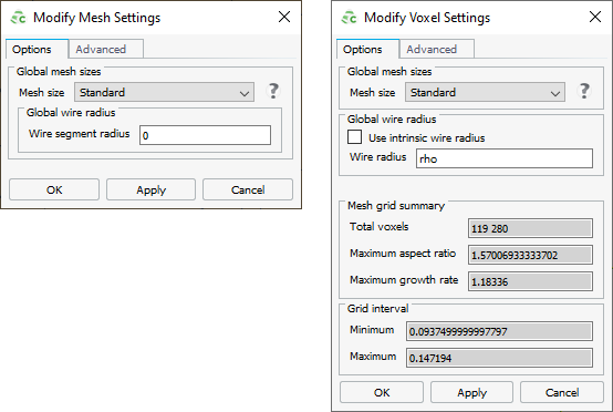
- On the Mesh tab, in the
Meshing group, click the
-
[Optional] Specify the parts to be meshed:
-
Specify the mesh size.
- To create a mesh using automatic mesh sizes, in the Mesh size field, from the drop-down list select Coarse, Standard or Fine.
- To create a mesh with a custom mesh size, in the Mesh
size field, from the drop-down list
select Custom. Specify the lengths applicable to the
model.
- In the Triangle edge length field, specify the triangle edge length.
- In the Wire segment length field, specify the wire edge length.
- In the Tetrahedron segment length field, specify the tetrahedron edge length.
- In the Voxel size field, specify the length for the voxel width, depth and height.
-
Specify the global wire radius.
- To specify a wire radius, clear the Use intrinsic wire radius check box and in Wire radius field, enter a value for the global wire radius.
- To allow the Solver to determine the wire
representation, select the Use intrinsic wire radius
check box.Tip: This option may improve the FDTD convergence.
Note: A local mesh refinement takes precedence over global mesh settings. - Click OK to modify the mesh and to close the dialog.