The example is intended for users with no or little experience with CADFEKO. It makes use of a completed rectangular horn model to familiarise yourself with model creation in CADFEKO and viewing the simulated results in POSTFEKO.
The example is intended for users with no or little experience with CADFEKO. This example is not an example intended for simulation, but rather to familiarise yourself with model creation in
CADFEKO.
Voltage sources and discrete loads are applied to ports and not directly to the model geometry or mesh. A port must
be defined before a source or load can be added.
When the frequency is set or local mesh settings are applied to the geometry, the automatic mesh algorithm calculates
and creates the mesh automatically while the GUI is active using default mesh settings. When required, these mesh
settings may be modified.
Launch the Solver to calculate the results. No requests were added to this model since impedance and current information are calculated
automatically for all voltage and current sources in the model.
Feko is a comprehensive electromagnetic solver with multiple solution methods that is used for electromagnetic field analyses
involving 3D objects of arbitrary shapes.
EDITFEKO is used to construct advanced models (both the geometry and solution requirements) using a high-level scripting language
which includes loops and conditional statements.
One of the key features in Feko is that it includes a broad set of unique and hybridised solution methods. Effective use of Feko features requires an understanding of the available methods.
Feko offers state-of-the-art optimisation engines based on generic algorithm (GA) and other methods, which can be used
to automatically optimise the design and determine the optimum solution.
Feko writes all the results to an ASCII output file .out as well as a binary output file .bof for usage by POSTFEKO. Use the .out file to obtain additional information about the solution.
CADFEKO and POSTFEKO have a powerful, fast, lightweight scripting language integrated into the application allowing you to create
models, get hold of simulation results and model configuration information as well as manipulation of data and automate
repetitive tasks.
When the frequency is set or local mesh settings are applied to the geometry, the automatic mesh algorithm calculates
and creates the mesh automatically while the GUI is active using default mesh settings. When required, these mesh
settings may be modified.
When the frequency is set or local mesh settings are applied to the geometry, the
automatic mesh algorithm calculates and creates the mesh automatically while the GUI is
active using default mesh settings. When required, these mesh settings may be
modified.
Open the Modify Mesh Settings dialog using one of the
following workflows:
On the Mesh tab, in the
Meshing group, click the Modify Mesh icon.
Press Ctrl+M to use the keyboard
shortcut.
On the Modify Mesh Settings, set the Mesh
size to Coarse.
Set the Wire segment radius to
0.001.
Figure 1. The Modify Mesh Settings dialog.
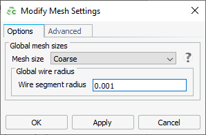
Click OK to create the mesh
and to close the dialog.