Quality criteria
1. Winding factors
For additional information, refer to section dedicated to the winding factor since it’s the same as Classical winding topology.
For unbalanced hairpin configurations, as the results are not relevant, therefore, they are not computed and displayed.
2. Slot star
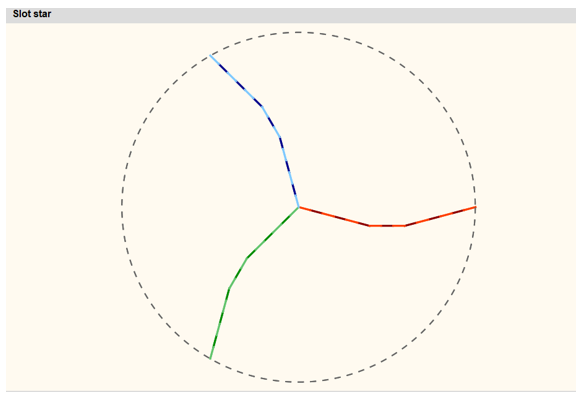
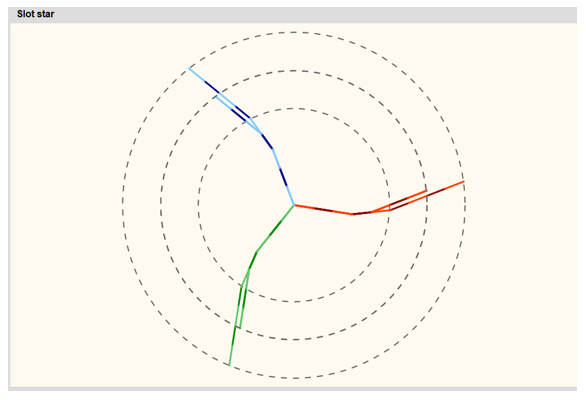
The Slot star represents the total vectorial sum of voltages, at the ends of each coil, for each parallel path.
A slot star is computed and displayed for each parallel path.
 |
|
| Slot star - Strong or weak balance case example | |
 |
|
| Slot star - Unbalance case example | |
| 1 | Balance analysis classification: - When the hairpin configuration is balanced (strong and weak balance), all the slot stars are superimposed (to differentiate strong and weak balance case referred to the table Parallel paths) When the hairpin configuration is unbalanced, there are as many different slot stars (circles) as there are different unbalanced parallel paths |
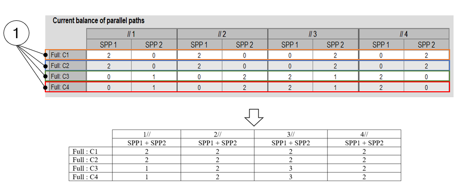
3. Parallel paths
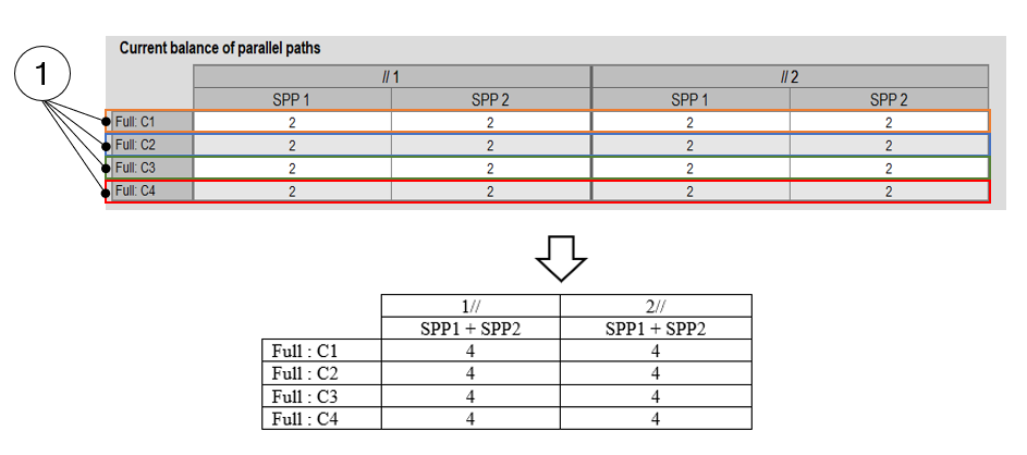
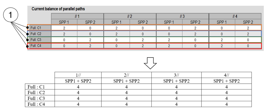
For each slot per pole and per phase of each parallel path, the number of conductors in each conductor layer is computed and displayed in a table
The three kinds of possible configurations in term of electrical current in parallel paths are illustrated below: Strong balance, weak balance and unbalance
 |
|
| Current balance of parallel paths – Strong balance case example | |
 |
|
| Current balance of parallel paths – Weak balance case example | |
 |
|
| Current balance of parallel paths – Unbalance case example | |
| 1 | Layer of conductors |
| 2 | Balance analysis classification: -
|
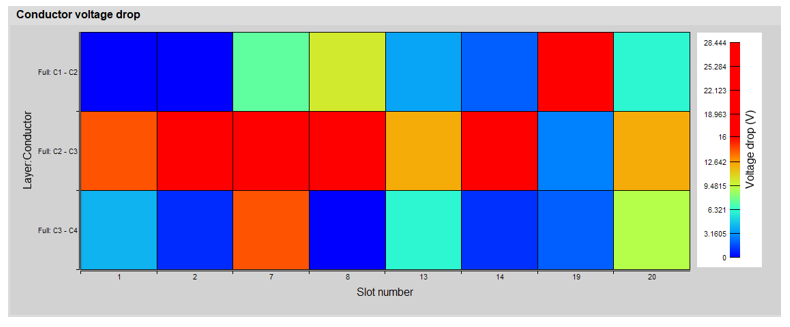
4. Voltage drop
 |
|
| Conductor voltage drop | |
| 1 | Inside each slot, the voltage drop between the superimposed conductors
for calculating the maximum Line-Line voltage value and the voltage drop
limit set by the user (X-factor: model evaluation table). This allows the user in visualizing quickly where are the hot point from an electrical potential difference point of view. |