Winding outputs
2. Definition – illustration
 |
|
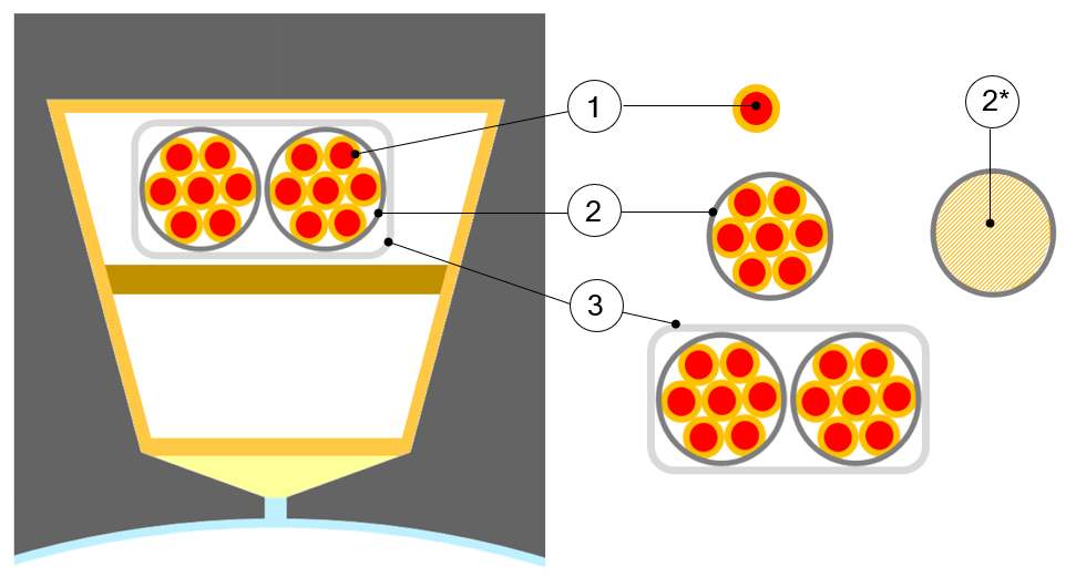
| Slot composition | |
| 1 | Wire also called strand. |
| 2 | Conductor. That also corresponds to a turn section (one conductor = one
turn). A conductor is composed with one or several wires in parallel. |
| 2* | The hatched area corresponds to the conductor’s useful area. Area which includes: the wires + insulation + free space. This is not the conductive area. |
| 3 | Coil which is an assembly of several conductors (i.e. several turns per coil). |
3. Inputs
| Label | Symbol | Tooltip, note, formula |
| Winding connection | Connect | Winding connection (Y – Wye or Δ - Delta) |
| Definition mode | * | Winding definition mode: Automatic, Easy, Advanced or Expert. |
| No. parallel paths | P paths | Number of parallel paths (all modes). |
| Phase sequence | * | Phase sequence (all modes). |
4. Settings – Coil – Conductor
| Label | Symbol | Tooltip, note, formula |
| No. turns per coil | Turns | Number of turns per coil. |
| No. wires in hand | No.Wires | Number of wires in parallel in a conductor (per turn) i.e. number of wires in parallel in each conductor. |
| Wire topology | * | Wire topology – Circular or Rectangular. |
| Wire diameter | ∅ wire | Wire diameter (without insulation). |
| Wire width | * | For rectangular shape type wire. |
| Wire height | * | For rectangular shape type wire. |
| Conductor topology | * | Cable topology – Circular or RectangularCoil conductors are grouped inside a circular shape or a rectangular shape. It is linked to the wire topology.Rectangular wires impose a rectangular cable. Circular wires impose a circular cable. |
| Conductor diameter | * | Cable diameter (without cable insulation) i.e. Diameter of the circle which are grouped inside all the coil conductors. |
| Conductor width | * | Cable width (without conductor insulation) i.e. Width of the rectangle which are grouped inside all the coil conductors - Case of rectangular shape type wire. |
| Conductor height | * | Cable height (without conductor insulation) i.e. Height of the rectangle which are grouped inside all the coil conductors - Case of rectangular shape type wire. |
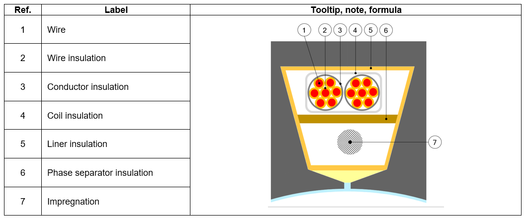
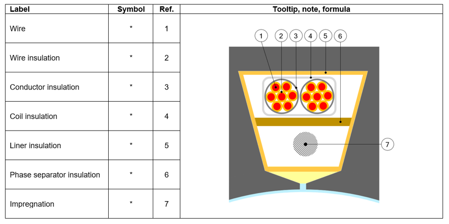
5. Setting – Coil Insulation thickness
For more details see section “Choice of winding MATERIALS”. All the thicknesses are defined as user input parameters in winding – Settings – Coil tab.
| Label | Symbol | Tooltip, note, formula |
| Wire | * | Insulation thickness of the wire |
| Conductor | * | Insulation thickness of the conductor |
| Coil | * | Insulation thickness of the coil |
| Liner | * | Insulation thickness of the liner |
| Phase separator | * | Insulation thickness of the phase separator |
| Impregnation | * | Insulation spread inside the slot |
| Impregnation goodness | * | Quality of impregnation (percentage of winding impregnation) |
 |
6. Settings – Coil – End winding
This part characterizes the end-winding and the resulting conductor dimensions.
For additional information refer to the chapter dedicated to the coil and conductor settings - End-winding topology and dimensions.
| Label | Symbol | Tooltip, note, formula |
| End-winding topology | * | End-winding topology: U-shape, C-shape or Y-shape. |
| C.S. total extension | * | Connection side total extension. |
| C.S. straight extension | * | Connection side straight extension |
| Axial overall length | * | Axial overall length. Length between the two extremities of the winding i.e. between connection side and opposite connection side. |
| O.C.S. total extension | * | Opposite connection side total extension. |
| O.C.S. straight extension | * | Opposite connection side straight extension. |
| Total conductor length | * | Total conductor length. |
| Mean turn length | * | Mean turn length. |
| Coil connection length | * | Additional length corresponding to the connections between coils. |
7. Settings – Calibration factors
| Label | Symbol | Tooltip, note, formula |
| Resistance factor | * | Setting of the “Resistance factor”. It allows adjusting computation result of resistance with resistance measurement. Thus, the resulting phase resistance value is considered wherever it is. |
| Inductance factor | * | Setting of the “Inductance factor”. It allows modifying the computation
result of end-winding inductance. Thus, the resulting end-winding inductance value is considered wherever it is. |
| Ref. temperature | * | The reference temperature. First, resistance values are always computed by considering a temperature equal to 20°C. However the user can also define his own reference temperature to compute the corresponding phaseresistance and Line-Line resistance values.Caution : This reference temperature is used only in the winding design environment. The test temperatures are defined in the test settings (refer to TEST chapter). |
8. Materials
This part characterizes the end-winding and the resulting conductor dimensions.
For additional information refer to the chapter dedicated to the coil and conductor settings - End-winding topology and dimensions.
 |