Advices for use
Structural data - Validity domain
- The number of slots can be chosen over the range [3, 2400].
- The number of poles can be chosen over the range [2, 400].
- The number of phases can be chosen over the range [3,15] in case of polyphase machines. Only odd values are considered.
- Range for number of slots [3, 90].
- Range for number of poles [2, 80].
- Range for number of phases [3,15] in case of polyphase machines
Working beyond these bounds is possible but accuracy of the results is the responsibility of the user.
Three tables representing a selection of combinations of number of poles and number of slots for the most typical number of phases (three, five and seven) are presented below.
In these tables the number of slots goes from n to 90 (with n the number of phases) and the number of poles goes from 2 to 80.
-
For three-phase machines, the grey cells correspond to combinations with a number of slots per pole per phase strictly lower than 0.25. These cases are not allowed by our process.Note: If the hairpin winding type is selected only configurations with an integer number of slots per pole and per phase are allowed.
- The black cells correspond to forbidden combinations from a technological point of view.
- The numbers indicated in the other cells correspond to reduction coefficients to
the resulting model in Altair Flux TM .
For example, “1” means that the whole geometry is represented. “2” means that only half of the machine is represented, and “n” means that the n th of the geometry is represented in the Flux®
That also gives a general idea of the size of the model in Flux® software. Higher value gives the reduction coefficient and faster computation for a given motor.
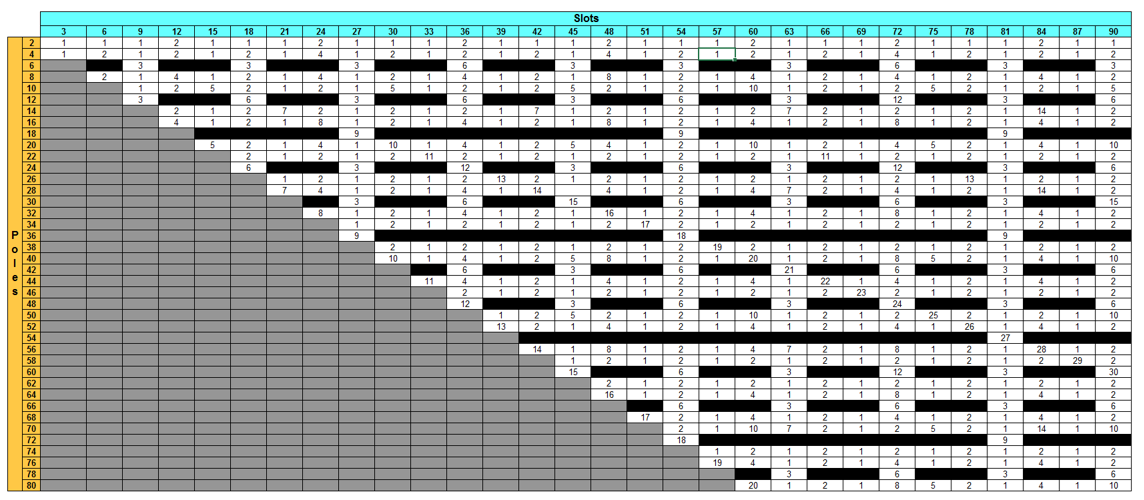 |
| Combinations No. poles / No. slots for a three-phase machine |
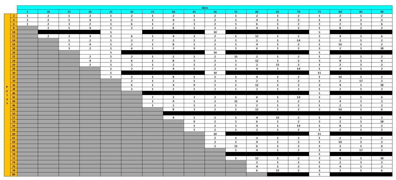 |
| Combinations No. poles / No. slots for a 5-Phase machine |
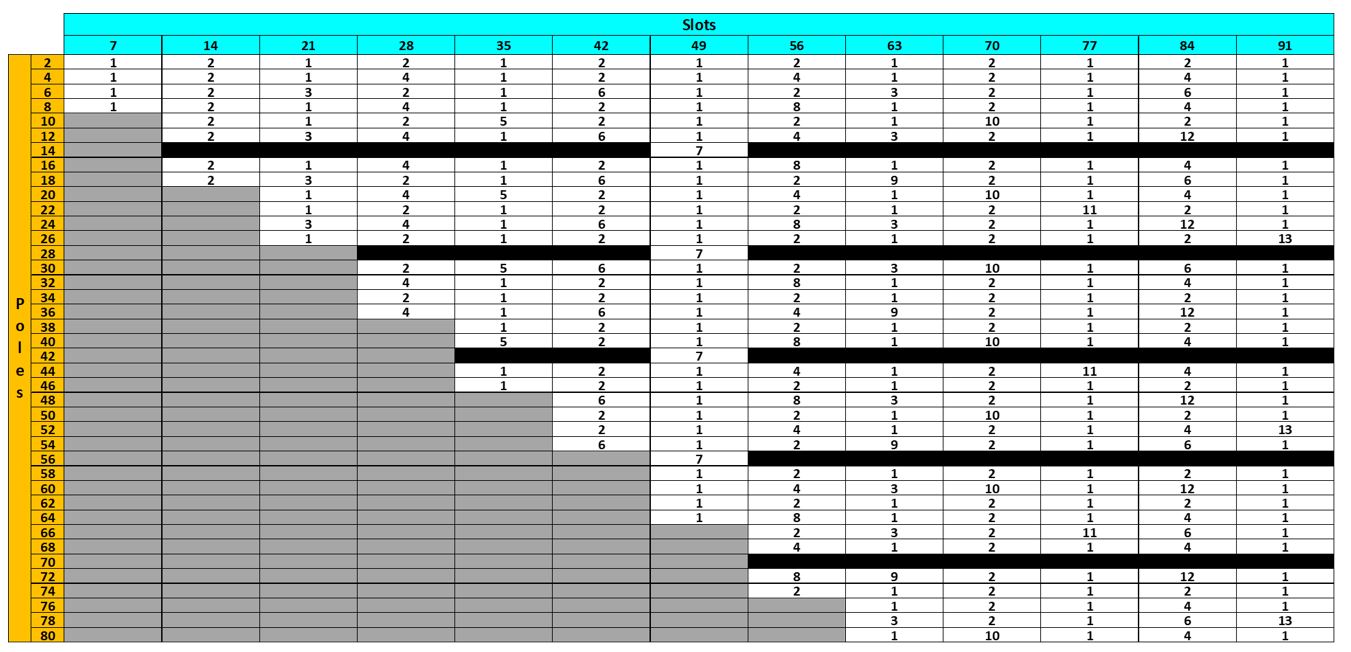 |
| Combinations No. poles / No. slots for a 7-Phase machine |
Layout of the winding – Winding connections
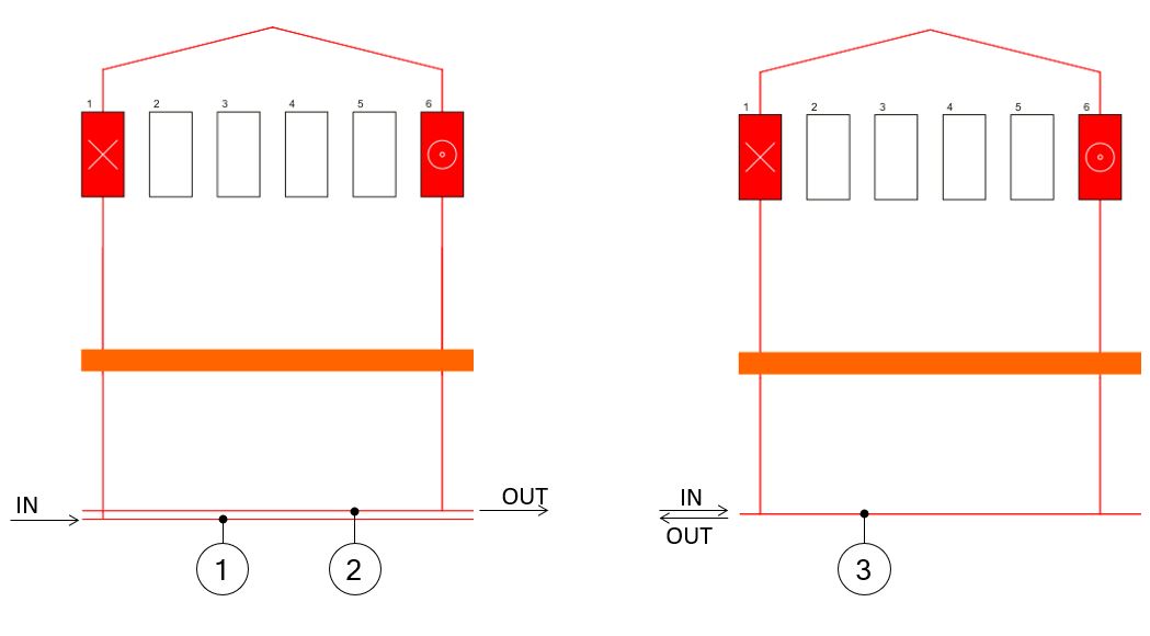
The representation of connections between coils and phases has been modified.
The lines that collect incoming and outgoing connections are merged into a single line. This has been done to make polyphase winding diagrams easier to read.
The picture below that illustrates the difference between the two representations.
 |
|
| Representation of the winding connections | |
| 1-2 | In previous versions, the two lines connection were represented. |
| 3 | In new versions, only one line corresponds to both IN and OUT connections |