Hairpin winding design
1. Preamble
In the software winding datasheet, the parameters written in blue correspond to user input parameters and the parameters written in black correspond to data resulting from computations.
The design and the export of projects from FluxMotor® to Flux®2D can be done. However, no test is available while considering a hairpin winding topology.
2. Differences with classical winding
The design of Hairpin winding type meet some limitations compared to the classical winding:
- Only 3-Phase winding is considered.
- Only integer number of slots per pole and per phase are allowed (fractional number are forbidden).
- A coil corresponds to one hairpin and not to an association of hairpins and back connections in serial.
- The hairpin which are associated in serial (thanks to back connections) are called parallel path or elementary coil.
- The number of turns in series per phase is defined by the number of conductors per layer, the number of layers and the number of parallel paths.
- Number of wires in hand is imposed to 1.
- Wire shape can be rectangular only.
- Insulation for conductors and coils are not available (please refer to the definition of coils and conductors).
- End winding shape can be Y shape only.
- New results of quality criteria dedicated to hairpin winding
are available:
- Current balance for parallel paths
- Voltage drops between conductors
- X-factor section gives an access to the inputs of the results “Conductor voltage drop”.
All these points are described in the following sections.
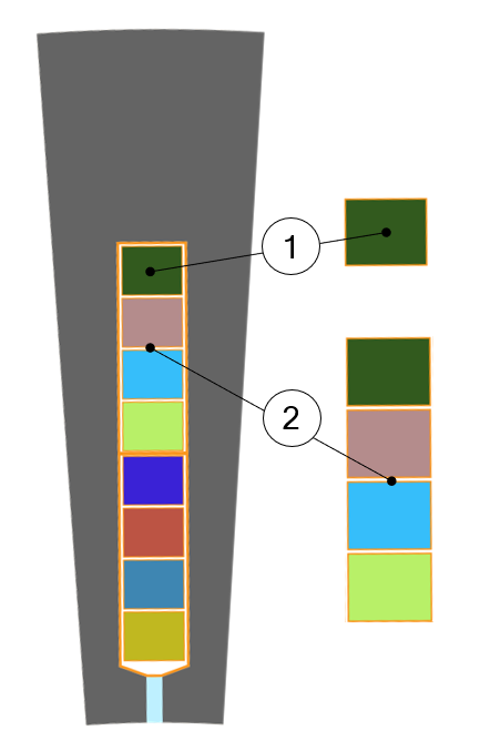
3. Terminology – Illustration
 |
|
| Slot composition | |
| 1 | Conductor (also called bundle). That also corresponds to a turn section (one conductor = one turn).For hairpin winding type, a conductor is composed with only one wire (one wire in hand). |
| 2 | A coil which is an assembly of several conductors (i.e. several turns per coil). |