Coil design
Overview - Definitions - Inputs
 |
|
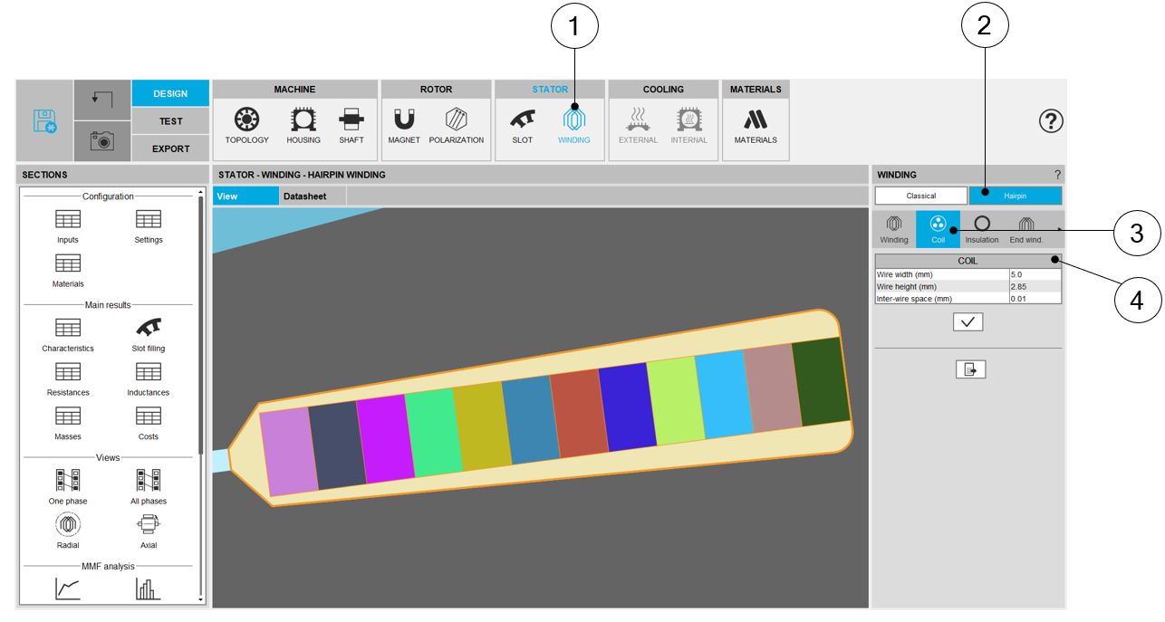
| Definition of the hairpin coil | |
| 1 | Selection of the STATOR subset: WINDING panel (Click on the icon WINDING). |
| 2 | Selection of hairpin winding technology. |
| 3 | Coil settings allow describing the coil composition (wires dimensions mainly) |
| 4 | Description of the coil dimensions (Width, height, inter wire space). |
The following inputs define the coil and how is filled the slots
| Label | Symbol | Tooltip, note, formula |
| Wire width | W wire | Wire width (without insulation), for rectangular shape wire |
| Wire height | H wire | Wire height (without insulation), for rectangular shape wire |
| Inter-wire space | w//w | Minimum distance between wires (with or without insulation) to be
considered for modelling inside the Flux2d environment. This parameter allows getting a better wire distribution inside the slot. |
Relevance of the slot filling
When the number of wires (induced by the number of conductors per layer and the number of layers) are higher than allowed by the slot free area, the wires are grayed in the slot filling view.
This is to inform the user that the number of wires must be decreased, so, with hairpin technology, the number of conductors per layer.
In that case, the design of the winding is not possible; the machine cannot be built or tested.
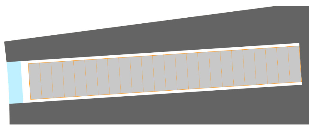 |
| Grayed rectangular shape type wire |
Motor Factory Design environment button and winding icon in the Stator section are colored in red. This means that there exist a fault in the design, which must be corrected.
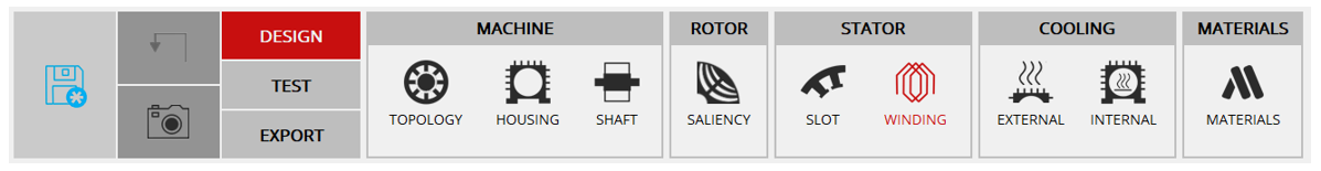 |
| Motor Factory Design environment button and the winding icon in the Stator section are colored in red.= a design fault must be corrected |
The tests cannot be performed; the tooltip message indicates that the slot filling is not valid, and the user must modify the slot filling parameters to unlock the test.
At the same time, a warning message indicates that there is not enough space for the specified number of wires. The allowed number of wires are mentioned in comparison with the targeted ones.
 |
| The tests cannot be performed |