Calibration factors
Overview - Definitions
| Label | Symbol | Tooltip, note, formula |
| Resistance factor | * | Setting of the “Resistance factor”: It allows modifying the computation
result of resistance. Thus, the resulting phase resistance value is considered. |
| Inductance factor | * | Setting of the “Inductance factor”. It allows modifying the computation
result of end-winding inductance. Thus, the resulting end-winding inductance value is considered. |
| Ref. temperature | * | The reference temperature: First, the resistance values are computed by
considering a temperature equal to 20°C. However, the user can also define his own reference temperature to compute the corresponding phase resistance and Line-Line resistance values. Note: This reference temperature is used only in the
winding design environment.The test temperatures are defined in the test
settings (refer to TEST chapter). |
Illustrations
 |
|
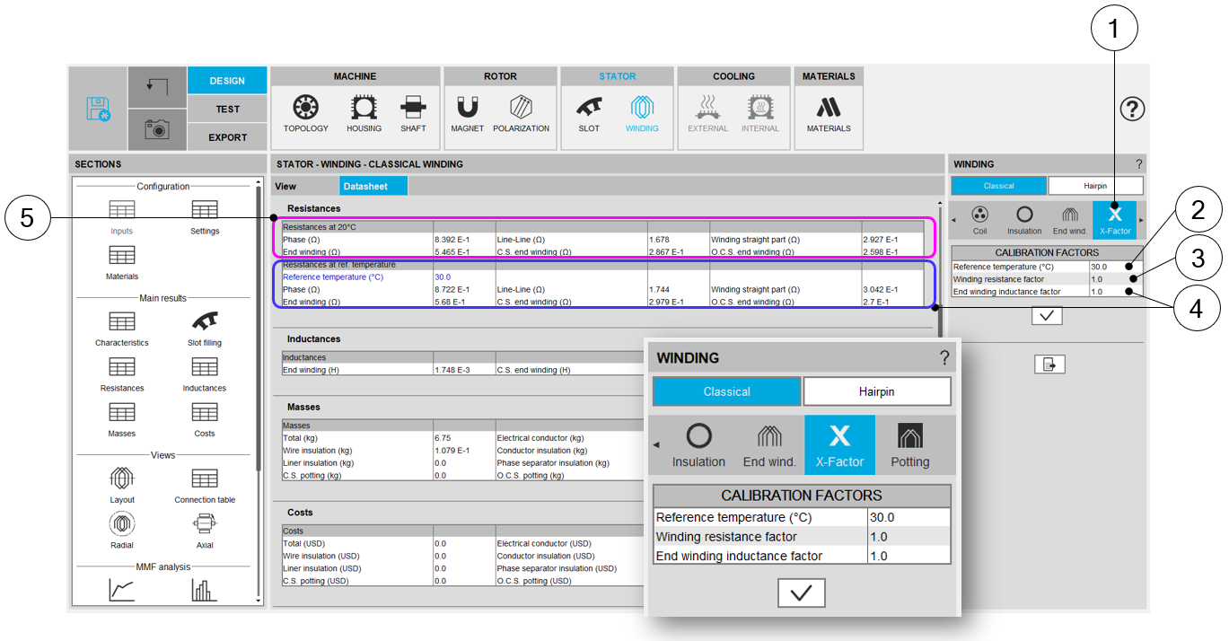
| Building the winding – X-Factor = Calibration factors | |
| 1 | Selection of the X-FACTOR section. |
| 2 | Setting of the “Resistance factor”. It allows adjusting computation
result of resistance. Thus, the resulting phase resistance value is considered. |
| 3 | Setting of the “Inductance factor”. It allows modifying the computation
result of end-winding inductance. Thus, the resulting end-winding inductance value is considered. |
| 4 | The reference temperature: First, resistance values are computed by considering a temperature equal to 20°C (5). However, the users can also define their own reference temperature to compute the corresponding phase resistance and Line-Line resistance values. |
| 5 | Resistance values for a reference temperature equal to 20°C. |
Warning - Negative end winding resistance with low value of X-Factors.
Here are a few explanations for this issue:
This issue has been introduced while considering the solid conductors inside the slot. Since the solid conductors are considered, the corresponding resistance (in the straight part of the machine) is deduced from the material properties and the size of the wires.
- Rphase 0 is the initial value of the phase resistance (with X-Factor = 1)
- RStraight 0 is the initial value of the phase resistance in the straight part of the machine (with X-Factor = 1)
- R end winding 0 is the initial value of the phase resistance in the straight part of the machine (with X-Factor = 1)
- Rphase 1 is the initial value of the phase resistance (with X-Factor ≠1)
- RStraight 1 is the initial value of the phase resistance in the straight part of the machine (with X-Factor ≠1)
- R end winding 1 is the initial value of the phase resistance in the straight part of the machine (with X-Factor ≠1)
The target is to get the following results:
(Rphase 1)=XFactor×(Rstraight 0)
With
(Rstraight 1)= (Rstraight 0)
- (R end winding 1)=XFactor×(Rstraight 0+R end winding 0)-(Rstraight 0)
- (R end winding 1)=Rstraight 0×(XFactor-1)+XFactor×(R end winding 0)
When X-Factor is very low, the end winding resistance can be negative.
We will reconsider how to apply the calibration factor to the winding resistance. Perhaps this will lead to applying the X-Factor only to the end winding and the winding connections not to then straight part.
Note that this problem doesn't impact the phase resistance value, nor the resulting computations, like the total Joule losses in the winding. (ref.: FXM-16113).