DC winding
Overview
This kind of winding architecture is used by DC machines to define rotor winding.
The DC winding has a lot of similarities with the 3-phase winding but also many specific traits when referring to architecture.
Therefore, only the architecture is described in this section since the coil, insulation, end-winding and x-factor tabs does not have any important modification when compared with the 3-phase classical winding.
For further information regarding basic knowledge and terminology about electrical winding, please refer to the previous sections which is dedicated to the winding design general user information.
Here is the homepage for the design of the rotor winding.
 |
|
| WINDING design area – Overview | |
| 1 | Selection of the ROTOR subset: WINDING panel (Click on the icon WINDING) |
| 2 | All the required user inputs to define the winding are available in the “WINDING” panel (right part). |
| 3 | Once a winding is defined, the corresponding results are
automatically displayed in the form of a winding report.
Visualization of the winding characteristics (inputs, settings,
materials, etc) are possible. Scrollbars allow browsing the whole document rapidly and giving an overview of all the results. Using scrollbars, complete data can be accessed and visualized. |
| 4 | Shortcuts for displaying the corresponding section of the winding report. |
| 5 |
A section scrolling bar allows choosing the section in which user inputs are defined. Scrolling selection bar where Winding architecture, Coil, Insulation, End-winding and X-Factor sections can be selected |
| 6 | Three modes of winding allow to define and build the winding architecture. |
| Auto | Automatic mode, used as default. |
| Easy | Easy mode, to choose solution among those FluxMotor® proposes. |
| Adv. | Advanced mode, to allow the user to define any specific input parameters. |
| 7 | User input parameter fields to enter the values according to the considered mode. |
Winding Architecture – Outputs
Outputs are quite like 3-phase winding, but some specific parameters arise when dealing with DC machine winding. For shake of completeness the parameters are listed in the tables below.
Characterization - Winding
| Label | Symbol | Tooltip, note, formula |
| No. poles | p | Number of rotor pole pairs. 2p = number of poles. |
| No. slots | Nslots | Number of stator slots |
| No. Layers | Nlayers | Number of layers – For a DC winding it is always equal to 2 |
| Winding type | * | The winding type: Lap or wave |
| Plex | * | The plex (simplex, duplex or triplex) |
| Coil connection | * |
Connection type: Progressive or regressive Progressive connection: Commutator segments are connected following the same direction as winding (i.e., commutator pitch is positive). Regressive connection: Commutator segments are connecting following opposite direction as winding (i.e., commutator pitch is negative). |
| Commutator pitch | Yc | Number of commutator segments between the segment connected to the coil input and the segment connected to the coil output. |
| No. parallel paths | Ppaths |
Number of parallel paths. For a wave winding it is equal to twice the plex. For a lap winding it is equal to number of poles * plex |
| Coil layout | * | Coil layout inside the slot – Full, Superimposed or Adjacent. |
| Throw (coil pitch) | * | Number of slot pitch between coil input and coil output. |
Characterization - Coil
| Label | Symbol | Tooltip, note, formula |
| No. turns per coil | Turns | Number of turns per coil |
| No. turns in series | N_turns |
Number of turns in series N_turns=N_coils/(2×P_paths ) |
| No. conductors | N_cond |
Total number of conductors N_coils=2×N_slots×Turns |
Lengths
| Label | Symbol | Tooltip, note, formula |
| Total conductor length | * | Total conductor length. |
| Mean turn length | * |
Mean turn length. |
| Coil connection length | * |
Additional length corresponding to the connections between coils and commutator segments. |
| Axial overall length | * | Axial overall length. Length between the two extremities of the winding i.e. between connection side and opposite connection side. |
Areas in slot
| Label | Symbol | Tooltip, note, formula |
| Conductive area | A_CondSlot | Conductive area inside one slot. A_CondSlot=A_Cond×Turns |
| Conductor conductive area | A_Cond |
A_Cond=Nwires×A_wire This area allows to compute the current density. |
| Wire conductive area | A_wire | Wire area (without insulation). |
| Slot area | A_slot | Slot area. |
| Insulation area | A_InsulSlot |
Insulation area inside one slot. One considers the slots of the machine where the number of coils are maximum. |
| Free area | A_Free | A_Free= A_slot- A_CondSlot- A_InsulSlot |
Fill factors
| Label | Symbol | Tooltip, note, formula |
| Conductive area | * |
Gross fill factor. Occupancy rate of the slot (conductive area only). (Conductor conductive area)/(Slot area)×100 |
| Conductor conductive area | * |
Net fill factor. Occupancy rate of the slot (conductive area + insulation area). (Conductor conductive area+insulation area)/(Slot area)×100 |
Resistances
| Label | Symbol | Tooltip, note, formula |
| Single coil resistance | * | Single coil resistance |
| Parallel path resistance | * | Resistance of one of the parallel paths |
| Total resistance | Total resistance of the machine at its terminals | |
| Winding straight part resistance | * |
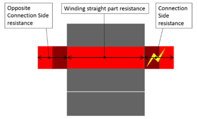 |
| End-winding resistance | * | |
| Connection side end-winding resistance | * | |
| Opposite connection side end-winding resistance |
Inductances
| Label | Symbol | Tooltip, note, formula |
| End winding | * | Total end winding inductance (including the two sides of the machine). |
| C.S. end winding | * | Connection side end winding inductance. |
| O.C.S. end winding | * | Opposite connection side end winding inductance. |
Masses and costs
Masses and costs
For additional information, refer to the sections dedicated to the coil and conductor settings and End-winding topology.
| Label | Symbol | Tooltip, note, formula |
| Total | * | Total winding mass. |
| Electric conductor | * | Conductive part mass. |
| Total insulation | * | Total winding insulation mass (wire + conductor + coil insulation + liner + phase separator). |
| Wire insulation | * | Wire insulation. |
| Conductor insulation | * | Conductor insulation. |
| Coil insulation | * | Coil insulation. |
| Liner insulation | * | Liner insulation. |
| Phase separator insulation | * | Phase separator insulation. |
| Impregnation insulation | * | Impregnation insulation |
| Wedge insulation | * | Wedge insulation, only when the slot topology contains a wedge |
Visualisation of the winding architecture
 |
| Visualization of the winding architecture |