Architecture
Overview – Definition
A DC winding is formed by as many individual coils as the number of slots of the machine. All these coils are identical except for an angular shift. Since the coils have an input slot and an output one, a slot will always have two coils wound inside it.
A key characteristic of a DC winding is that, unlike the 3-phase one, a coil is characterized (other by its input and output slots) by the two commutator segments connected to it (one for the input side and a second for the output side). These commutator segments will connect the coil to the brushes and, therefore, to the DC source feeding the machine.
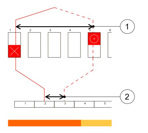
- The throw – The coil pitch number of slot pitch between coil input and coil output.
- The commutator pitch: number of commutator segments between the segment connected to the coil input and the segment connected to the coil output.
 |
|
|
Graphic example of a reference coil with a throw 4 and a commutator pitch 1 This winding corresponds to a lap winding, simplex with progressive coil connection (see below) |
|
| 1 | Throw |
| 2 | Commutator pitch |
- Lap winding: The ends of one coil are connected to consecutive commutation segments (i.e., the commutator pitch absolute value is equal to 1 for simplex winding)
- Wave winding: The ends of one coil are connected to commutator segment separated by an angular distance as close as two pole pitch as possible (for simplex winding)
For both winding types, the throw is usually as close as possible to a pole pitch.
- The plex defines the number of commutator segments in contact with the same brush at a given time. It has a great influence on the number of parallel paths and, therefore, on the machine back EMF and the maximum current.
- The coil connection can be progressive and regressive: In a progressive connection the commutator segments are connected following the same direction as the winding (i.e., commutator pitch is positive) while in a regressive connection the commutator segments are connected following opposite direction as the winding (i.e., commutator pitch is negative).
More information about these variables is included in the next sections.