Finite-State Machine Mass Spring Damper System
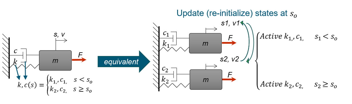
Consider the following mechanical system: A 1DoF mass spring damper system that switches between two different stiffness and damping coefficients {k1, c1} and {k2, c2} depending on the system position, s, which is a state variable of the system along with the mass velocity, v.
The following system can be modelled using an equivalent set of two mass-spring-damper systems where on each timestep only one is active depending on set condition, in this case the system’s position, s.
The two models communicate by exchanging the full states vector when the switching condition is met. Thus, the previously deactivated model, once activated, gets updated by the states of the previously active one.
On this example, we are going to model such a system by combining romAI with the State Machine library from Twin Activate using the finite-state machine logic.
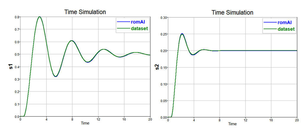
First, we start by training two romAI models, one for each spring-damper combination {k1, c1} and {k2, c2}.
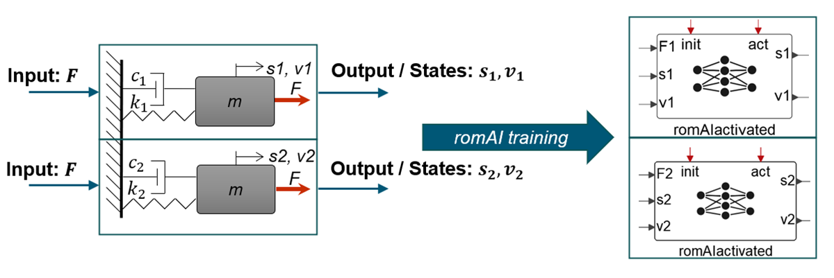
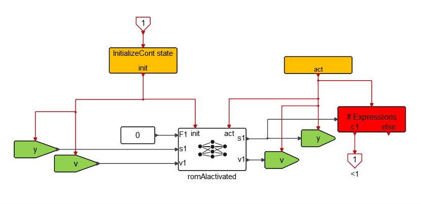
For the romAI model deployment, select the Use Activated romAI option to make the block externally activated and expose the state variable reset values and condition.
Use the Top_Cont_SM_Diagram block template from the State Machine library to build the model with two states. States refer to the finite-state machine, not to be confused with the state variables of the system.
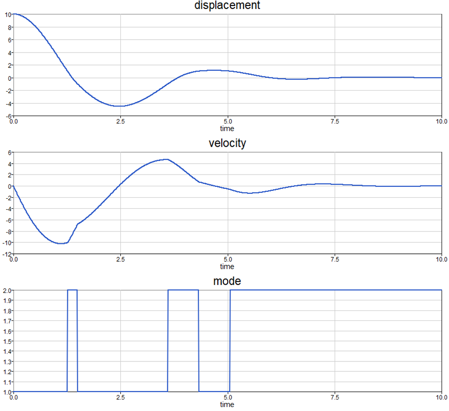
The switching condition is given by the absolute value of the system’s position, s, so that when |s|≥1 State #1 is active, otherwise State #2 is active.
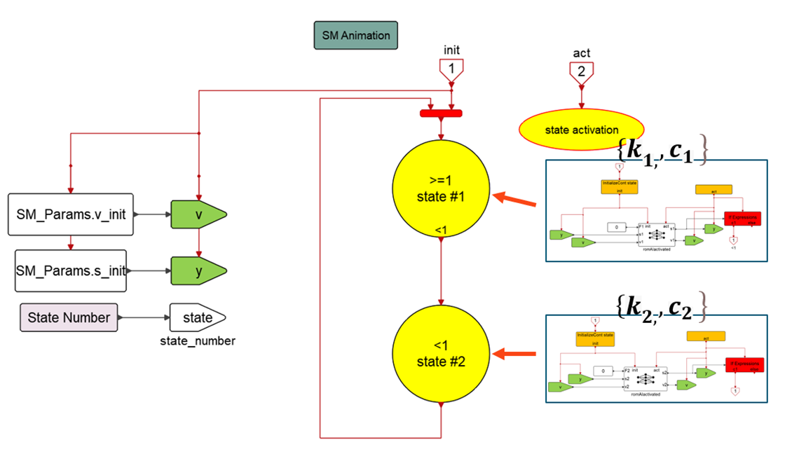
When the switching condition is met, an activation event is generated that is sent on the initialization port of the corresponding Activated romAI block and also activates the GetSignal blocks that receive the updated state variables. They are updated by SetSignal blocks from the previously active model.
To simulate the system, give an initial condition on the displacement, sinitial=10 (from Model Context) while keeping the external Force, F=0. The results from the combination of the two romAI activated blocks are merged into a single output and shown below. The mode variable is corresponding to the active state of the finite-state machine diagram (#1 or #2).