Solid Pipe
![]()
Dialog Box
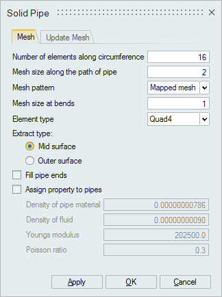
Mesh
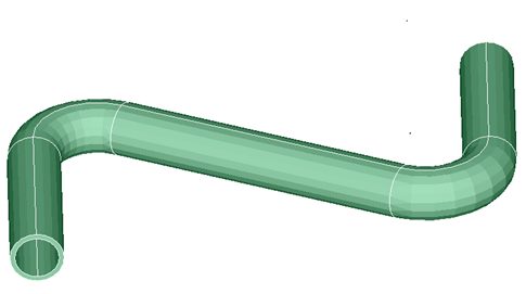
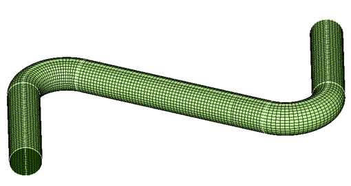
Mid or outer surface mesh of pipes can be created automatically from CAD body using this tool. Mid or outer surface mesh will be created using "Mesh size along the path of pipe" and "Number of elements along the circumference". "Mapped mesh" pattern will create 100% Quad4 or Tri3 elements based on the user defined element type on the mid or outer surface for pipes and hoses. Bends of the pipe can be meshed with finer mesh size using "Mesh size at bends". The pipe ends can be filled using the option "Fill pipe ends". This tool allows to assign material to the pipe mesh. If the fluid density is to be included for analysis, specify the fluid density and the software will adjust the pipe density to include the fluid mass.| Input | Output |
|---|---|
|
|
Update Mesh
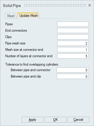
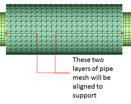
In order to accurately interpret the results at the junction of pipe and connector, mesh of pipe needs to be refined at the end. A specific number of QUAD layers can be created at connector ends by specifying the number of layers and mesh size at connector ends.
| Input | Output |
|---|---|
|
|
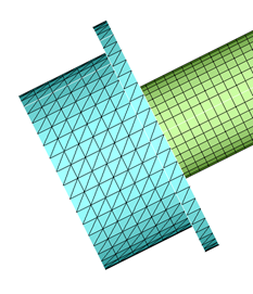
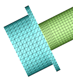
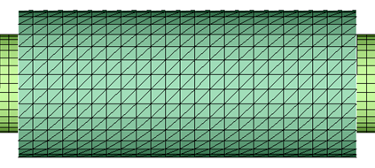
The QUAD mesh in pipe may not aligned with those in the support body. The mesh on the pipe is adjusted to align with the mesh of support.
| Input | Output |
|---|---|
|
|
The overlapping cylinders between pipes, end connectors and clips will be identified based on the value of tolerance.