Map Faces
![]()
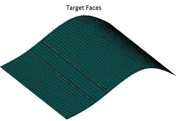
Introduction
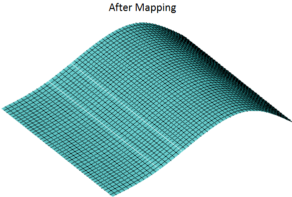
The Map tool is used to map the mesh from one set of faces to another set of faces. Map mesh finds application in creating mapped meshes for manual hex meshing. There is two types of mapping:
- Basic
- Advanced
Basic
Basic option allows user to map the mesh from one set of faces to another set of faces. The input faces should be four-sided and four-edged or three-sided and three-edged.
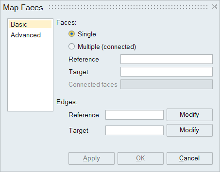
Basic map mesh can be used in following two ways:
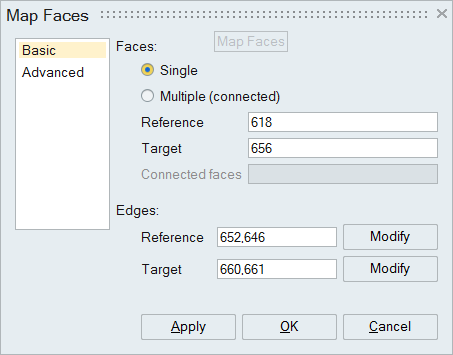
- Single: Select one source and one target face.
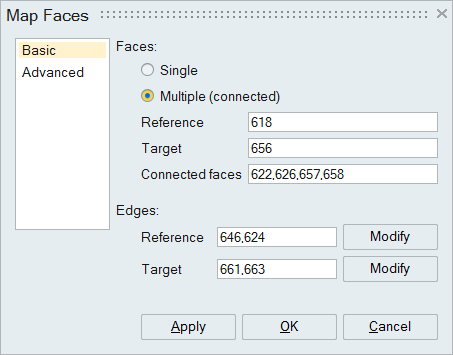
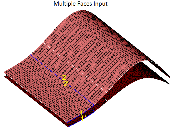
- Multiple: Select one source and one target face, then select the remaining faces as Connected faces.
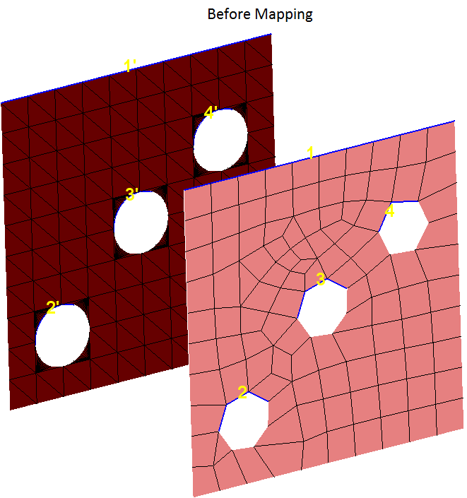
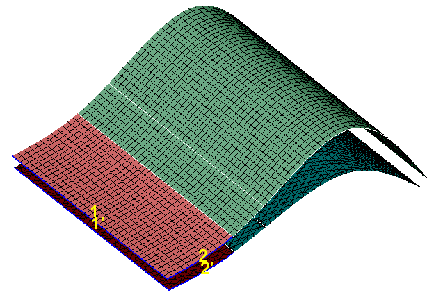
Direction edges will be identified automatically, when the input faces are selected. Source and Target direction edges are highlighted in UI. First direction edges are highlighted with numbers 1 and 2. Second direction edges are highlighted with numbers 1" and 2". If the automatic edge identification is wrong, then the user can click the modify button in the corresponding direction edges and manually select the edges.
Limitations:
- Supported only for FEM entities.
- Source direction edges should be selected from the source face only and they should share one common vertex. Same condition is applicable for target direction edges.
- Order of direction edges should be same for both source and target faces.
- All the faces should belong to same model.
Steps:
- Select two or more faces(4-sided and 4-edged faces or 3-sided and 3edged faces)
- If multiple faces are selected, select the direction edges from the source and target face from the corresponding face pair.
- Click Apply.
- If map mesh goes wrong, click undo to bring back the old face.
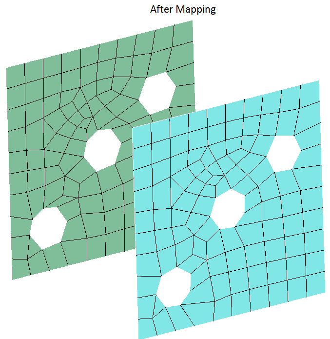
Example:
- Single face map
- Multiple face map
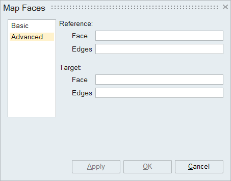
Advanced
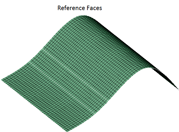
Advanced map mesh allows the user to map the mesh for non four-sided faces also. User can give the reference face followed by reference direction edge and choose the target face followed by target direction edge. Advanced map mesh supported only for planar and partial cylindrical faces.
Limitations:
- Automatic identification of edges is not available for this case. User has to pick the reference and target direction edges manually.
- Supported only for a set of faces. Edges should be identical in both the faces.
- All the faces should belong to same model.
Steps:
- Select the reference face and direction edges.
- Select the target face and direction edges.
- Click Apply.
- If map mesh goes wrong, click undo to bring back the old face.
Example: