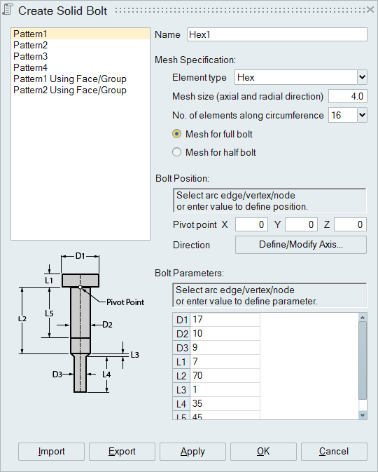
Create Solid Bolt
![]()
Description
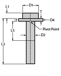
User can create four different patterns of HEX/TET bolt by defining corresponding parameters. User need to define the axis and pivot point before defining other parameters. User can pick an arc/vertex/node to define the parameter.
If an arc is selected to define D1/D2/D3/D4, diameter of that arc will be assigned to the parameter. Selecting a node/vertex to define D1/D2/D3/D4 will calculate the shortest distance between that to the axis of the bolt and assign to the parameter.
If an arc is selected to define L1/L2/L3/L4/L5/t, distance is calculated by projecting the center of the arc to the axis of bolt. Selecting a node/vertex to define L1/L2/L3/L4/L5/t will project that to the axis of bolt and calculate the distance. L5 is the distance at which the pretension section will be created.
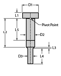
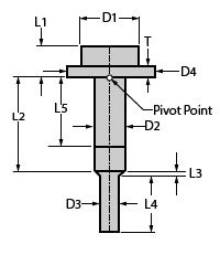
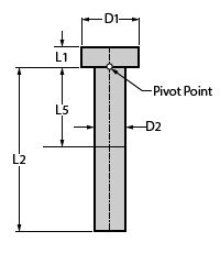
| Pattern 1 | Pattern 2 | Pattern 3 | Pattern 4 |
|---|---|---|---|
|
|
|
|
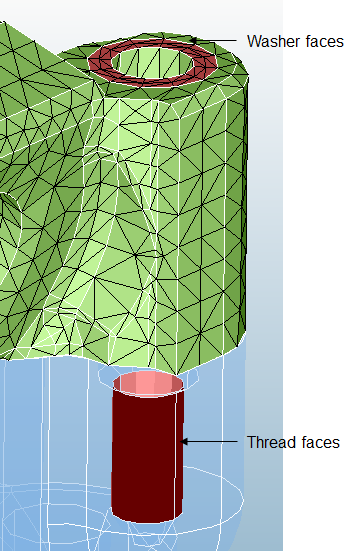
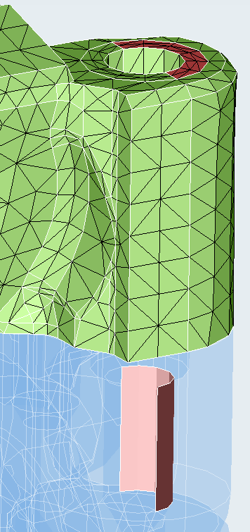
Create bolt using face/group option
"Pattern 1 Using Face/Group" and "Pattern 2 Using Face/Group" are similar to "Pattern 1" and "Pattern 2" respectively, but the input to create bolt differs. Washer faces/face group and thread faces/face group are the input. Half of the washer and thread face can also be given as input. The parameters to create the bolt are calculated based on the input faces. The value of D1 of Pattern 1 Using Face/Group and the value of D4 of Pattern 2 Using Face/Group is the outer diameter of washer. User can also define their own value for D1 and D4. D2 will be calculated based on the option and the diameter (D3) of threaded face
D2 = D3 - (2 x Shrinkage) or D2 = D3 x Ratio
L5 will be considered as (L2+L3)/2 automatically otherwise user can define a value for it.
Bolts which are created using "Pattern 1 Using Face/Group" and "Pattern 2 Using Face/Group will have matching nodes on washer and threaded faces.
|
|
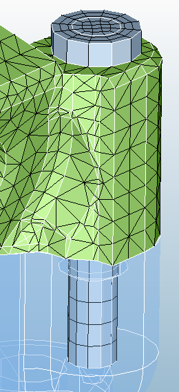
Higher order bolts using washer and thread faces
If the input faces contain higher order elements, then the bolt mesh will also be higher order.
Matching mid nodes of the bolt mating facesAfter creation of higher order bolt, the mid nodes of the bolt mating faces are automatically matched to the corresponding mid nodes on the input faces.The user can enable or disable this matching mid nodes feature by enabling the environment variable SL_BOLT_MIDNODE_MATCHING. It is set as true by default.
Assumptions for mid node matching: The input faces must be iso mesh