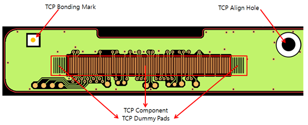
TCP component is a tape carrier package. TCP align hole is used to fix the TCP
components.
The TCP Align Hole dialog contains the following
sections:Figure 1.
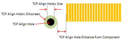
TCP Align Hole Definition: TCP align hole can be defined with the hole size
and distance from the TCP component. Figure 2.
Definition with Hole Size: Define the align hole with its size.
Using the floating value input tool, set the size or range of hole
size.
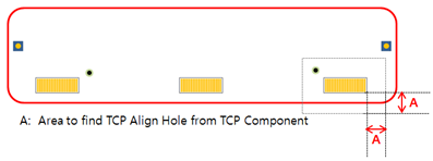
Define with Distance from TCP Component Group: TCP align hole should
not be apart from the TCP component. They should be placed close
together.Figure 3.
Component Group: Select the TCP component group from the
component group list.
Maximum Distance: Set the maximum distance between the TCP
component and the TCP align hole.
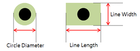
Silk Hole Mark Definition: TCP align hole can have two types of shapes for
silkscreens: circle and line types. Define the diameter and width/height
value for the circle and line types.Figure 4.
Circle Diameter: Set the circle diameter for the circle type
silkscreen.
Line: Set the line type silkscreen with its width and length.
Width: Set the width of line for line type silkscreen.
Length: Set the length of line for line type
silkscreen.
TP(Test Point) Definition: To check the clearance between a TCP align hole
and a test point, set the test point components.
TP Component Group Selection: If test points are registered with
footprint, select the test point component group from the component
group list.
Pads’ Diameter in Routing: If test points are used with pads, set
the size of the pad diameter.
Via’s Diameter: If test points are used with vias, set the size of
the via diameter.
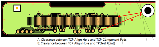
TCP Align Hole Clearance Checking: Check clearances between the TCP align
hole and the TCP component pad/test points in the design.Figure 5.
Clearance between TCP Align Hole and TCP Pads: Set the clearance
value between the TCP align hole and the TCP component pads.
Clearance between TCP Align Hole and TP (Test Point): Set the
clearance value between the TCP align hole and the test points.
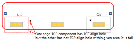
Existence Check for both Edge Components: Check if all edge TCP
components have a TCP align hole within the given area. Hole
searching area is defined in the TCP Align Hole Definition. If one
of them doesn’t have a TCP align hole, it is a fail.Figure 6.
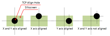
Silk Hole Mark Alignment with TCP Align Hole: Check if the TCP align
hole and silkscreen are aligned along the given axis.Figure 7.
X: Check if the TCP align hole is aligned with silkscreen
along the X-axis. If they are not aligned along the X-axis,
it is a fail.
Y: Check if the TCP align hole is aligned with silkscreen
along the Y-axis. If they are not aligned along the Y-axis,
it is a fail.
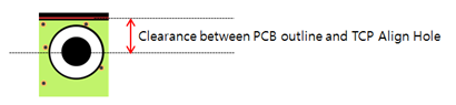
Clearance between PCB Outline to TCP Align Hole Center: Set the
clearance value between the TCP align hole and the PCB outline.Figure 8.
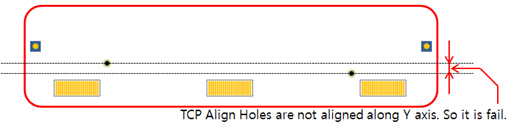
Alignment between Side Edge TCP Align Holes: Check if the side
edge’s TCP align holes are aligned with each other along the
Y-xis.Figure 9.
Tolerance: For the two location values, if they are less
than the tolerance, PollEx DFM
recognizes them as the same value.
X/Y: Select alignment axis.
Number of TCP Align Holes’ Counting: Check the number of TCP align
holes in the design. Choose the maximum/minimum/same value counting
condition.