Revolve Geometry
Revolve surfaces, nodes, lines, elements, or facets around a defined axis.
-
From the Topology ribbon, Extrude/Revolve tool group, click the
Revolve tool.
Figure 1. 
- Optional:
On the guide bar, click
 to define additional options.
Tip: Click to define the Biasing
method and Biasing intensity for the element/facets selection.
to define additional options.
Tip: Click to define the Biasing
method and Biasing intensity for the element/facets selection.Figure 2. No Biasing 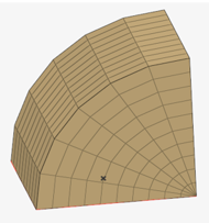
Figure 3. Linear Biasing 
Figure 4. Exponential Biasing 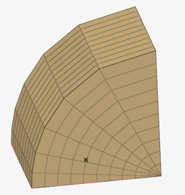
Figure 5. Bellcurve Biasing 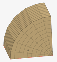
- Choose between Surfaces, Nodes, Lines, Elements, and Facets using the guide bar selector.
- Select surfaces/nodes/lines/elements/facets in the modeling window.
- Click Axis on the guide bar.
- Left-click to place the axis.
-
Revolve your selection by
dragging the slider or entering an angle in the microdialog.
Tip: Click
 in the microdialog to define the direction of the axis using the Vector
tool. Once a direction has been defined, press Esc.
in the microdialog to define the direction of the axis using the Vector
tool. Once a direction has been defined, press Esc.Enter the density value in the microdialog for elements / facets selection to Specify the number of elements to generate along the path of the revolve.
- Check Create mesh to automatically open the 2D meshing tool after creating surfaces. After you finish meshing, exit the tool to return to Geometry.
-
On the guide bar, complete one of the following:
- Click
 to apply and stay in the tool.
 - Click
 to apply and close the tool.
 - Click
 to exit the tool without applying.
- Click
Note:
- For the nodes input, based on the geometry creation mode defined, either a CAD surface or an FE geometry surface is created. While using the Revolve tool for lines or surfaces, the input determines whether a CAD surface or an FE geometry surface is created. For example, CAD lines are created as CAD surfaces, FE geometry edges are created as FE geometry surfaces.
- FE geometry solid creation for elements/facets selection is not supported at this time.
- A revolve preview for FE geometry solids is not supported at this time.