Extrude Geometry
Extrude lines, nodes, surfaces, elements, or facets along their normal direction, a vector, or another line.
-
From the Topology ribbon, Extrude/Revolve tool group, click the Extrude tool.
Figure 1. 
- Optional:
On the guide bar, click
 to define additional options.
Use the FE tab for additional options related to FE geometry.
to define additional options.
Use the FE tab for additional options related to FE geometry. -
Choose between Lines, Nodes,
Surfaces, Elements, or
Facets using the guide bar selector.
Note: If Nodes is selected, a line is drawn through the specified nodes before extruding.
Elements and Facets are enabled if the Mesh checkbox is selected..
-
Select lines/nodes/surfaces/elements and facets and
extrude in the
following ways:
- Use the drop-down in the microdialog to extrude at a fixed normal distance or at a variable distance.
- Click
 to define a direction using the Vector tool. Once a direction is defined, manipulate the
slider or enter a value in the microdialog.
to define a direction using the Vector tool. Once a direction is defined, manipulate the
slider or enter a value in the microdialog. - Activate the Guides selector to extrude along selected guiding lines.
Use the options in the microdialog to define how the
geometry is extruded.
- Fixed Frame
- The geometry is only translated during the extrude, not rotated.
- Line Tangent
- In addition to the translation of the fixed frame option, the geometry is also rotated in the same way that the tangent of the line list rotates.
- Frenet Frame
- In addition to the translation and rotation of the Line
Tangent option, the geometry also rotates around the line
list tangent axis in the same way as the curvature vector
rotates.
The Frenet Frame option does not work well when the curvature of the line list is not smooth or includes large jumps.
- Reverse Direction
- Defines the extrude in the opposite direction.
-
Select Mesh to create mesh along with geometry.
Note:
- Extruding Elements and Facets creates solid elements without geometry.
- For surfaces, click
 to change between Hex
and Bounding mesh option.
to change between Hex
and Bounding mesh option. - Hex creates solid elements with geometry whereas Bounding creates 2D mesh on the solid surfaces.
-
On the guide bar, complete one of the following:
- Click
 to apply and stay in the tool.
 - Click
 to apply and close the tool.
 - Click
 to exit the tool without applying.
- Click
A extrude preview for FE geometry solids is not supported at this time.
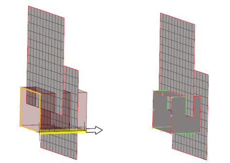
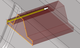
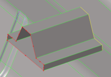
Auto-Trim
Use the auto-trim ![]() option in the microdialog when extruding nodes and lines.
option in the microdialog when extruding nodes and lines.
While extruding lines or nodes, if a continuous surface or mesh is intersected and this option is ON, the newly created surfaces are trimmed at the intersection. The auto-trim option works for both geometry intersecting geometry and mesh. It also works for FE topology intersecting FE topology.
 |
 |
 |
Hex Meshing
Use the Extrude tool to create a mesh of solid elements.
While the Solid Map tool can automatically create 3D mesh directly on solids as long as the solids you select are already mappable, hex meshing depends on an existing 2D mesh, which is then extrapolated into a 3D mesh based on the parameters you input.
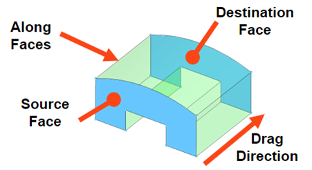
- Two opposing faces are called "Source" and "Target" faces.
- One or more faces that directly connect and enclose the volume between the source and target are called "Guide" faces.
- The drag direction is the vector from the source face to the destination face.
Create Hex Mesh
-
From the Topology ribbon, Extrude/Revolve tool group, click the Extrude tool.
Figure 10.
- From the guide bar, select Mesh.
-
Choose between Surfaces,
Elements, or Facets using the
guide bar selector.
Note: Select source geometry that defines the source face of the 3D volume. These can be surfaces, elements, or 2D/3D topological faces.
- Optional:
On the guide bar, click to define additional
options.
The following advanced options are available:
- Apply orthogonally along extrusion
- Keep the solid elements generated more perpendicular to the surface faces in the along direction.
- Optimize hex elements
- Optimization is performed to improve Jacobian and warpage quality. Avoids negative Jacobian elements.
-
Create hex mesh in one of the following ways:
Option Description Along vector - In the microdialog, set a density value or an element size if not already defined in the options menu.
- Enter a thickness value or drag the manipulator to create hex
mesh along the element normal.
The biasing style works in conjunction with biasing intensity. If the intensity is "0", biasing is not applied.
Figure 11. No Biasing 
Figure 12. Linear 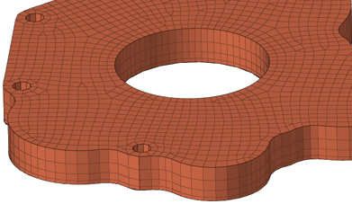
Figure 13. Bell Curve 
Figure 14. Exponential 
Tip:- Click to pick the global X/Y/Z,
screen normal, screen parallel, and/or a
user-defined direction instead.
- Click
 to flip the normal
direction.
to flip the normal
direction.
- Click
Figure 15. 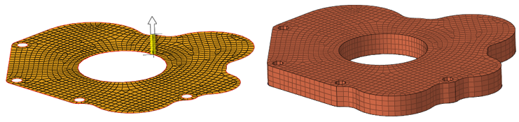
Figure 16. . 1D elements converted to 2D elements along a vector. 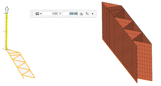
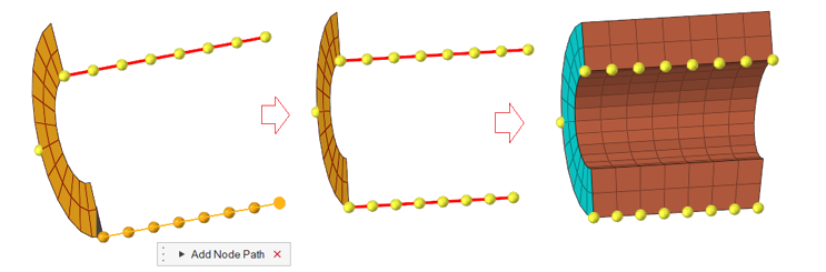
With Guides/Targets (Optional) - Click the Guides selector.
- Select the geometry that defines the face of the 3D volume along
which you wish to map the mesh.
When elements are used, the mapped mesh maintains the nodal positions with selected elements. They can be equivalenced to have common nodes. While selecting nodes, each selection should represent an edge that connects the source and destination.
- Click the Target selector.
- If desired, select geometry that you wish the 3D mesh to match
up with.
Figure 17. 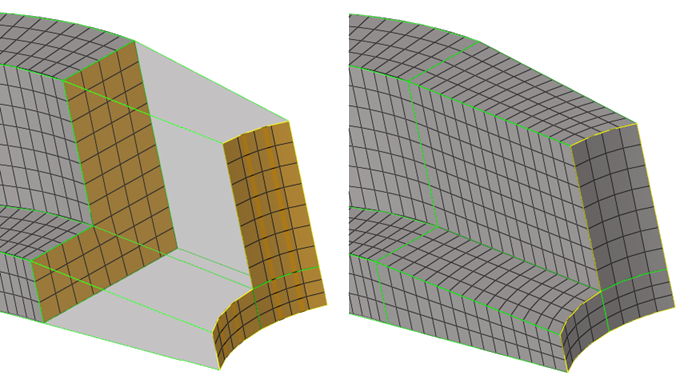
- In the microdialog, set a density value or an element size if not already defined in the options menu.
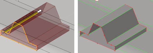
Figure 18. . Mesh created with source elements and a midline as a guide. 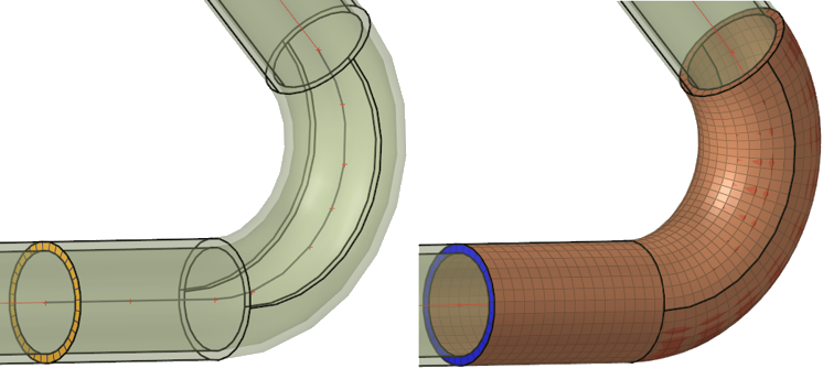
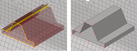
Figure 19. . Mesh created with source elements and surfaces/lines as guides. 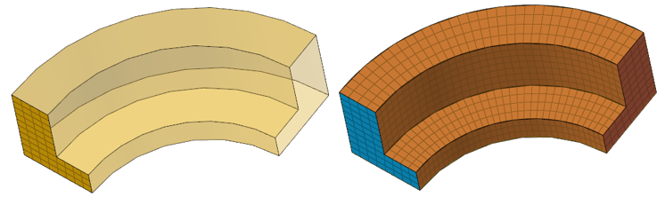
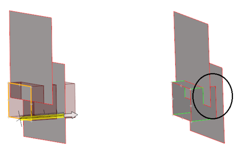
Figure 20. . Mesh created with source elements and multiple faces and elements as guides. Topo(2D/3D) element faces are supported. 
Figure 21. . Mesh created with source elements and multiple node paths as guides.