Geometry Preferences
Define geometry preferences.
From the File menu, select to define the following geometry preferences.
- Geometry Cleanup Tolerance
- Set the cleanup tolerance to Automatic or Manual.
- Face Selection
-
- Geometry feature angle
- Determines when to add (creating two surfaces from one) or remove (merging two surfaces into one) a new vertex to model geometry.
- Geometry Creation
-
- Auto-stitching
- For tools that use surface creation, determine how new
surfaces are created and stitched to the model.
- Within same component
- Auto-stitch created surfaces to adjacent surfaces that belong to the same component.
- Across any component
- Auto-stitch created surfaces to all adjacent surfaces.
- From attached to selection
- Stitch created surfaces to the surfaces attached to the selected surfaces or edges.
- From selection only
- Only stitch created surfaces to other selected surfaces, or surfaces that have edges or vertices selected.
- Create mode
- Create surfaces as CAD or FE geometry.
- Create in
- Choose a method for organizing the geometry.
- Current
- Organize new geometry in the current component.
- Original
- Organize new geometry in the same component to which the selected geometry belongs. The surface is kept in the component that is chosen first.
- New
- Organize new geometry in the new part.
- Display
-
- Surface lines
- The default number of u-v lines to draw on new
surfaces.Note: Displaying surface lines helps visualize a surface better, but it can slow down the redraw speed of a large model. Use the Surf Lines panel to change the number of surface lines on existing surfaces.
- CAD
-
- Show updates immediately
- CAD models from Inspire can read
parameters. This option immediately runs Inspire in the background to update
the geometry as changes happen. Note: From the Topology ribbon, Edit pull-down menu, use CAD Update to make changes and update the geometry only once.
- Inspire installation directory
- To update CAD geometry in Inspire, specify the Inspire installation directory path.
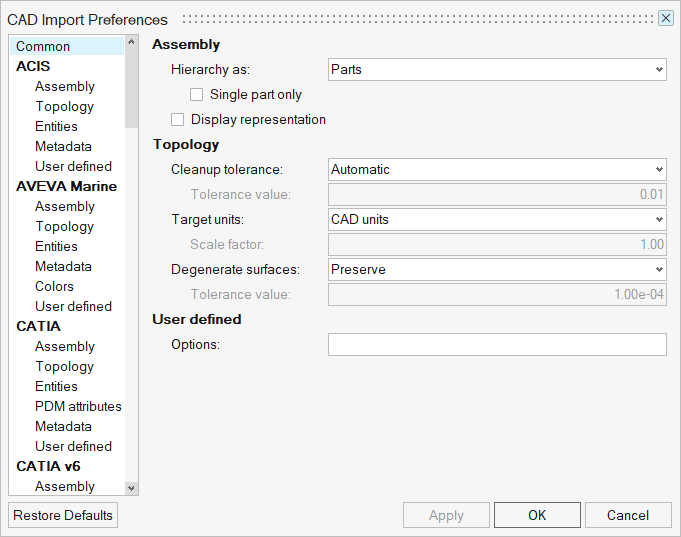
- Import Options
- Click Import Options to display the
CAD Import Preferences dialog.
Figure 1.