Offset Geometry
Use the Offset tool to offset surfaces, solids, lines, elements, or faces.
Note: The Offset tool supports splines and ellipses.
-
From the Topology ribbon, click the Offset tool.
Figure 1. 
-
Set the guide bar selector to
Lines, Surfaces,
Solids, Elements, or
Faces.
Option Description Lines - Select free lines to offset.
- Click
 on the guide bar and define the following options:
- Link type
- Choose how the offset is generated when there is
a discontinuity (other than 180 degrees) in the
direction of the curvature of the input line list,
that is, when input lines do not connect with each
other.
- interpolate
- Interpolate the offset direction on both sides
of the discontinuity to allow a smooth transition.
In this case, along the interpolation region, the
offset direction will be different than the
curvature direction. Amplified fluctuations, which
would occur in the offset because of small ripples
in the input curve, are smoothed out with this
option.
Figure 2. 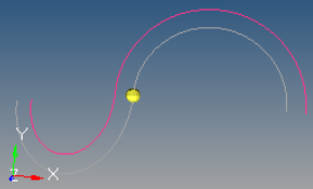
- insert link
- Insert a straight line segment as a link
between the offset of input lines, if there is a
jump in offset direction at points where the input
lines meet.
Figure 3. 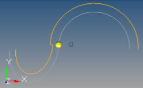
- no link
- Do not insert a link if there is a jump in
offset direction at points where input lines meet.
In this case, the offset lines may become
disconnected.
Figure 4. 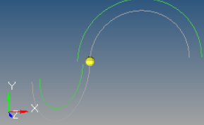
- Enter an offset distance in the microdialog. Use the icons to toggle between a uniform offset or a linear offset based on a start and end value.
- Optionally, you can choose to switch the starting point of the
line list or delete the original lines after offsetting on the
guide bar.
The start of the line list is indicated by a red arrow at the end of the chain.
Note:- Closed lines are treated as if they were not closed so that the offset creates open lines.
- Successive offsets (4-5 offsets, one after other) or very large offset values of some lines become sensitive to approximation errors or invisible fluctuations in the line.
Surfaces and Solids - Select surfaces or solids to offset.
- If desired, select Continuous offset on the guide bar to preserve the connection between adjacent surfaces after offsetting. For surfaces, you also have the option to define separator lines.
- Click-and-drag to offset or enter a value in the microdialog.
Note: The topology of the surface edges (free, shared edges, and so on) is maintained during the offset function. Some individual surfaces will be trimmed or extended to maintain the connectivity.Elements and Faces - Select elements or faces to offset.
- Click on the guide bar and define the following options:
- Layer type
- Solid, Thicken shell, shell, and shell offset.
- Thickness method
- Total thickness/Offset Distance: specify the total thickness of the layers of solid elements you want to create or specify a fixed distance to move the elements in case of shell offset.
- Click-and-drag to offset or enter a value in the microdialog.
- Define the number of layers.
- Optionally, click
 to define the
corner type.
to define the
corner type. - Optionally, click
 to reverse the
direction.
to reverse the
direction.
-
On the guide bar, complete one of the following:
- Click
 to apply and stay in the tool.
 - Click
 to apply and close the tool.
 - Click
 to exit the tool without applying.
- Click
Tip: Offset geometry in the opposite normal direction by entering a negative
offset value.