Import Geometry Sections
Instead of defining Geometry using EDEM, you can import Geometries from a variety of CAD applications.
-
Right-click Geometries and then select Import
Geometry.
- To import a single Geometry, navigate to the file that you want to import then click Open.
- To import multiple Geometries, navigate to the list of files that you want to import and select multiple files by pressing the Ctrl key and left-clicking to select each file, or press the Shift key to select files.
-
In the Geometry Import Parameters dialog box, specify
the following details:
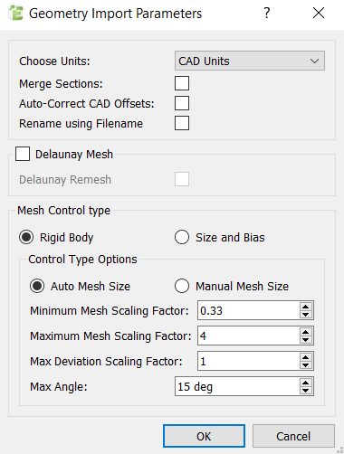
For Specify Choose Units Specify the unit of measurement for the Geometry. Optionally, select CAD Units, and the units used in the CAD file will be interpreted appropriately. Note: It is recommended to specify the units as some CAD formats do not save any SI units system in the file.If you have selected multiple Geometries, they will be imported with the same units.Note: If the Geometries have been created with different units, you must import them separately.Merge Sections Select the checkbox to merge separate Geometry sections into a single section. If you have selected multiple Geometries, select the checkbox to merge separate Geometry sections into a single section.Note: If the Geometries are in separate files, they will not be merged. Only Geometries in the same files will be merged.Auto-Correct CAD Offsets Select the checkbox to align the CAD origin position in EDEM. Rename using Filename Select the checkbox to rename the imported Geometries from the CAD file. -
Select the Mesh Control Type (these options do not affect pre-meshed
objects):
- Rigid Body
For Specify Auto Mesh Size The Auto Mesh Size uses the characteristic length as a reference point for the CAD import. For more information about how these settings are defined as a scaling factor of the characteristic length, see Calculate Characteristic Length . Minimum Mesh Scaling Factor Indicates the minimum acceptable element size. This is a multiple of the characteristic length.
Maximum Mesh Scaling Factor Indicates the maximum acceptable element size. This is a multiple of the characteristic length. Note: If there is no limit to the required maximum element size, you can set the size to a very large value.Max Deviation Scaling Factor Indicates the acceptable deviation between the element edge and the surface edge. To meet this requirement, the lengths of the element edge along a curved surface edge are reduced as specified by the lower limit. This is a multiple of the characteristic length. Max Angle Indicates the maximum angle across which elements can be maintained. When the normal angles of two adjacent elements exceed this angle, a new set of nodes is created between them to maintain clean feature lines. Using a higher value may result in elements spanning the feature line. Manual Mesh Size Uses the actual length as the settings for the mesh elements. Min Size Indicates the minimum acceptable element size. This uses an absolute value. Max Size Indicates the maximum acceptable element size. This uses an absolute value. Note: If there is no limit to the required maximum element size, you can set the size to a very large value.Max deviation Indicates the acceptable deviation between the element edge and the surface edge. To meet this requirement, the lengths of the element edge along a curved surface edge are reduced as specified by the lower limit. This uses an absolute value. Max Angle Indicates the maximum angle across which elements can be maintained. When the normal angles of two adjacent elements exceed this angle, a new set of nodes is created between them to maintain clean feature lines. Using a higher value may result in elements spanning the feature line. - Size and Bias
For Specify Element Size Indicates the average element size. The length of any active (shared or free) surface edge divided by the element size determines the number of elements to be placed along that edge.
- Rigid Body