Description
Overview
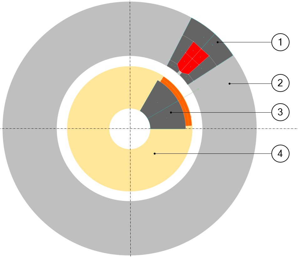
Different types of parts are considered like for instance, outer slot and inner magnet.
Outer slots are defined in the outer ring of the machine and inner magnets are defined in the inner ring of the machine. Each of them is described in a sector, as shown in the picture below. The same principle is applied for all kinds of parts (slots, magnets, bars, saliencies, and poles).
 |
|
|---|---|
| 1 | Outer slot (1) defined in the outer ring (2) of the machine. |
| 2 | Inner magnet (3) defined in the inner ring (4) of the machine. |
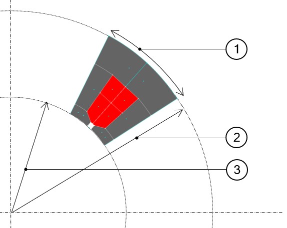
Structural data
- Inner diameter of the sector
- Outer diameter of the sector
- Slot number or magnet number, driving the angular opening of the sector.
This information is called structural data of the part. See the illustration of the sector shown below.
 |
|
|---|---|
| 1 | Angular opening of the sector. |
| 2 | Outer diameter of the sector. |
| 3 | Inner diameter of the sector. |
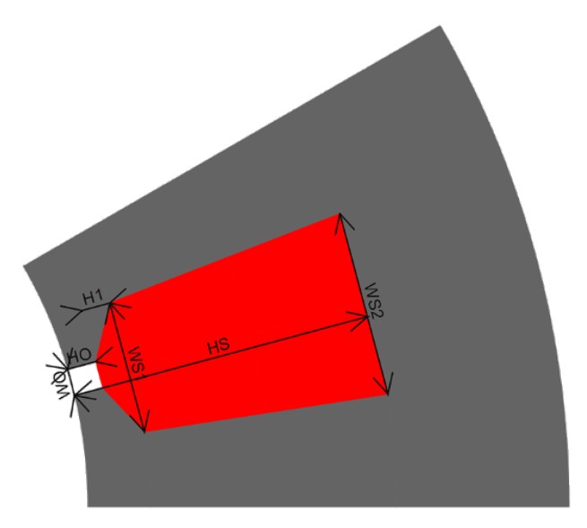
User parameters
All the parts can be parameterized so that the dimensions can be modified by using user parameters. These dimensions of the part are defined inside the sector (that is, by considering the structural data).
Constraints
Constraints can be imposed on a part to control the use of user input parameters.
For example, a slot height cannot be greater than the thickness of the stator outer ring.
 |
|
|---|---|
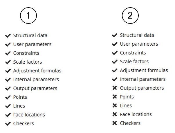
| 1 | On the left side, all the steps are validated, and the part can be used in Motor Factory |
| 2 | On the right side, the part is not yet finished and cannot be used in the Motor Factory |
When all the items of the status are not validated, then it is illustrated in the list shown above, but some icons are also modified as indicated below.
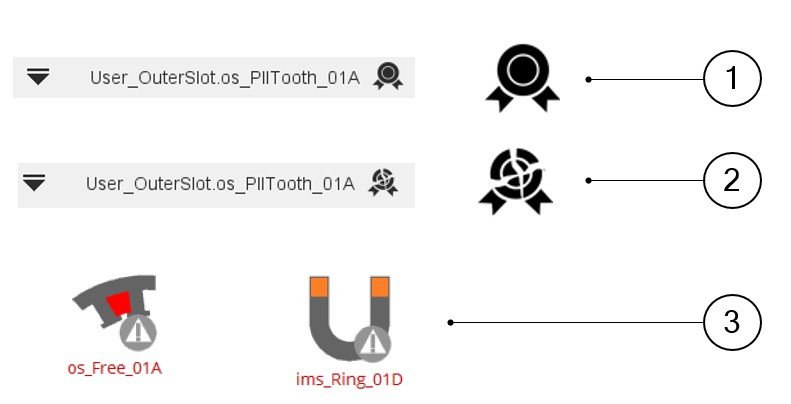 |
|
|---|---|
| 1 | Case where the part is valid and can be used in the Motor Factory. |
| 2 | The icon on the right top part of the Part Factory environment shows a broken illustration. In that case the part is not valid and cannot be used in Motor Factory. |
| 3 | Thumbnails to illustrate a non-validated outer slot and non-validated inner magnet. |
Details
The parts data are grouped in a section and named as “Details”.
- Name of the part
- Name of the corresponding library
- Type of library
- Type of sector (Inner, Outer)
- Symmetry (Yes, No)
- State (Qualifiable or Not qualifiable)
- Version of the model used to build the parts in Part Factory.
Depending on the type of part, other information is displayed. For example, the type of design such as toothed winding design or consequent pole depends upon whether it is a slot or magnet.
Dimensions on drawing
The entire user input parameters as well as the output parameters can be illustrated in the drawing.
The elements needed to define arrows attached to the dimensions are located at the end of the Excel file, where all the properties of the part are described.
However, this information is not available from Part Factory.
Only the results can be shown.
Clicking on user input parameters or output parameters makes the corresponding dimension appear on the drawing.
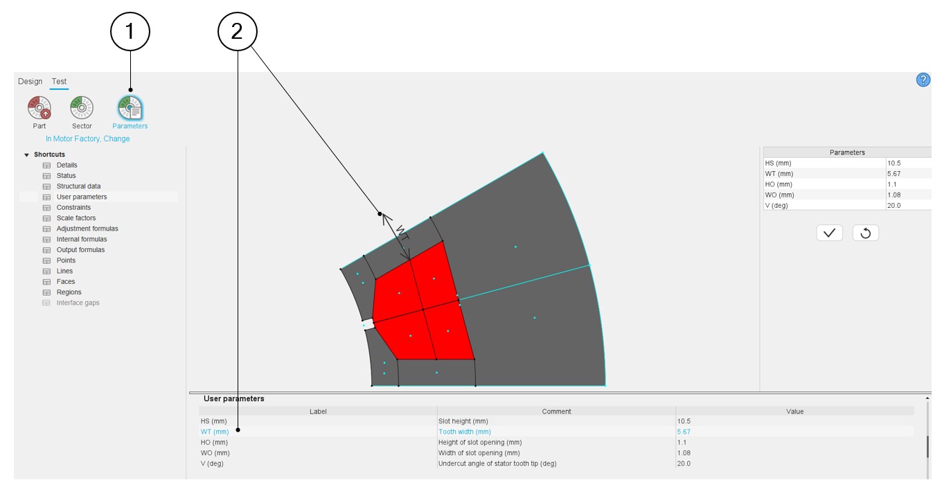 |
|
|---|---|
| 1 | From the test environment, simulate the change of the user parameters in Motor Factory to evaluate the good behavior of the parameterized part. |
| 2 | Visualization of the user’s parameters. |