Geometry
The basic elements needed to build a part are the points, the lines, the faces and the regions.
Points
This section contains the coordinates of all points needed to build the part. These coordinates are written by considering Cartesian coordinate system and Polar coordinate system.
Below are the examples of coordinate systems for the description of slots (Symmetric or non-symmetric). The same principle is also used for magnets.
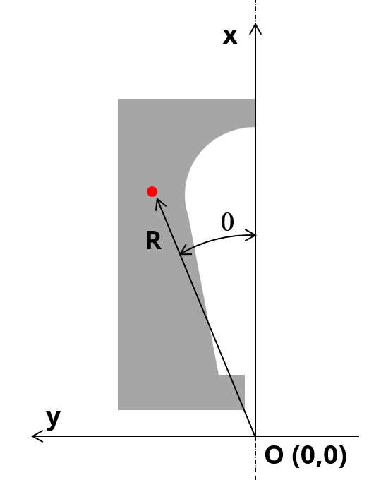 |
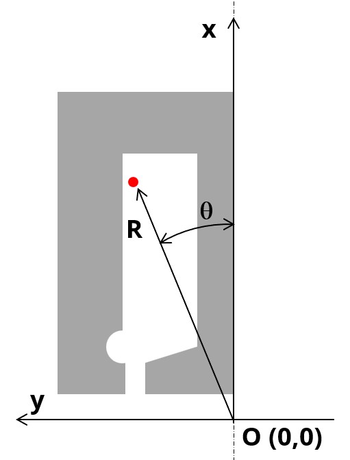 |
|---|---|
| Symmetric part | Non-symmetric part |
- Visible, to be used by visible and invisible lines
- Invisible, to be used by invisible lines
- No exist, for arc centers
All the visible points must belong to a sector.
Superimposed points are forbidden.
Lines
This section contains a description of all the lines used in the part model.
Lines only depend on points and sector points.
- Segment (straight lines defined with only two extremity points)
- Arc (defined in Counterclockwise direction, with starting, ending and center points)
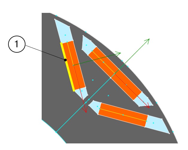
- "Visible" to separate two faces having different properties (faces with different natures, lines separating coil conductor regions in 4 zones for adjacent and superimposed winding for example, or for lines separating the airgap from the stator or the rotor etc.).
- "Invisible" when lines do not have to be considered in the "part" model. An invisible line won’t be represented in the finite element model of the part.
- “No exist” when the corresponding line will be used as a support to illustrate the polarization of magnets, for example. A “No exist” line will be neither used to build the geometry of the part nor to represent in the finite element model of the part.
Faces and regions
This section contains a description of all the faces and regions defined and used in the part model.
Each face is defined by a location point. The coordinates of these points are defined in a general coordinate system (Cartesian or polar) as it is described above for points.
The point must be within the corresponding face for all the values of user input parameters.
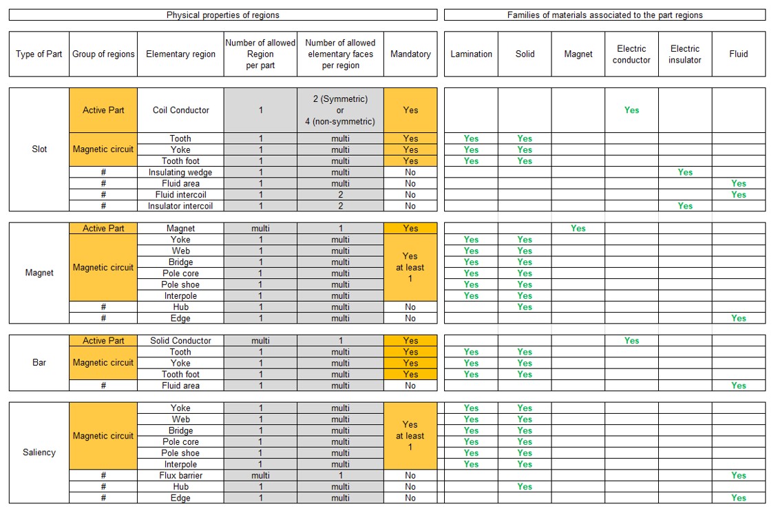
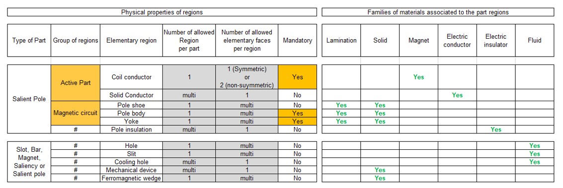
Each face has a label and a nature. The nature of faces defines the corresponding regions.
The physical properties of regions are linked to the materials that can be used to build them.
The table below gives the physical properties of slots and magnets.
Interface gaps
"Interface gaps" regions allow describing thin regions between faces inside the topology of parts.
It can be needed, for example, to represent the glue layer or a very thin airgap between two ferromagnetic regions.
Parametric data
The part topology can be parameterized. Dedicated sections are provided to allow users to manage this according to the need. One section to do this is called “Internal formulas”. It allows describing all the needed formulas or expressions to define the part topology from user input parameters.
Two other sections, “Scale factors” and “Adjustment formulas”, can be used when the considered part has the capability to adapt itself automatically to the sector in which it will be imported.
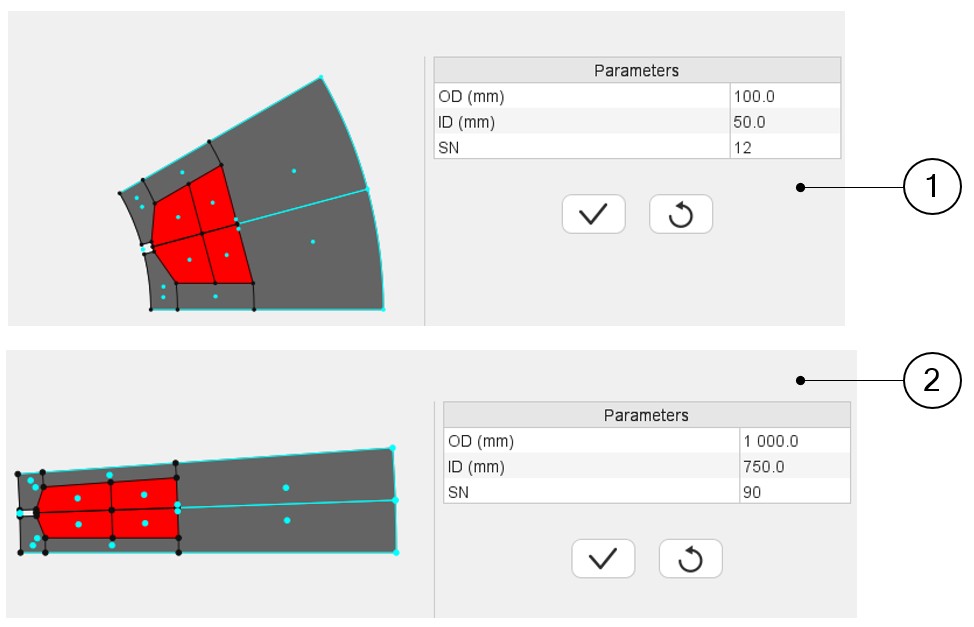
- Outer diameter =100
- Inner diameter = 50
- Number of slots = 12
- Outer diameter =1000
- Inner diameter = 750
- Number of slots = 90
The aim of these two sections is to define transformation formula that allows an automatic adaptation of the part when it is imported into a new sector with differences between original and final structural data.
A dedicated tutorial is provided to explain the principles for applying these rules.
 |
|
|---|---|
| 1 | Topology and dimensions of a slot with an original set of structural data |
| 2 | Topology and dimensions of a slot with a new set of structural data. The geometry automatically adjusts. |