Thermal diagram
Frame external area
- Frame to external fluid total thermal resistance in temperature-speed area
This map shows the global thermal resistance used in FluxMotor® model between the frame and the external fluid in a temperature - speed area.
The frame temperature, shown on the X-axis, impacts the natural convection and radiation occurring on each of the frame surfaces (higher is the frame temperature and higher is the temperature difference between the frame and the external fluid).
The map is plotted for a frame temperature going from the external fluid temperature to 150 K above this reference temperature.
The machine rotation speed, shown on the Y-axis, can impact the forced convection when the user chooses a tip speed ratio to define the force convection.
The global resistance between the frame and the external fluid shown on this graph corresponds to the thermal resistance network shown below.
Three main paths extract the heat from the machine to the external fluid, corresponding to three main components: the straight part of the frame and the two end caps.
Each of these paths extracting heat from the machine is composed of several thermal resistances.- The conduction through the material composing the part
- The convection and radiation occurring from the external surfaces of the frame.
In this network, the convection resistances are mixes of natural and forced components of the convection phenomenon.
Figure 1. The global resistance between the frame and the external fluid - Thermal resistance network 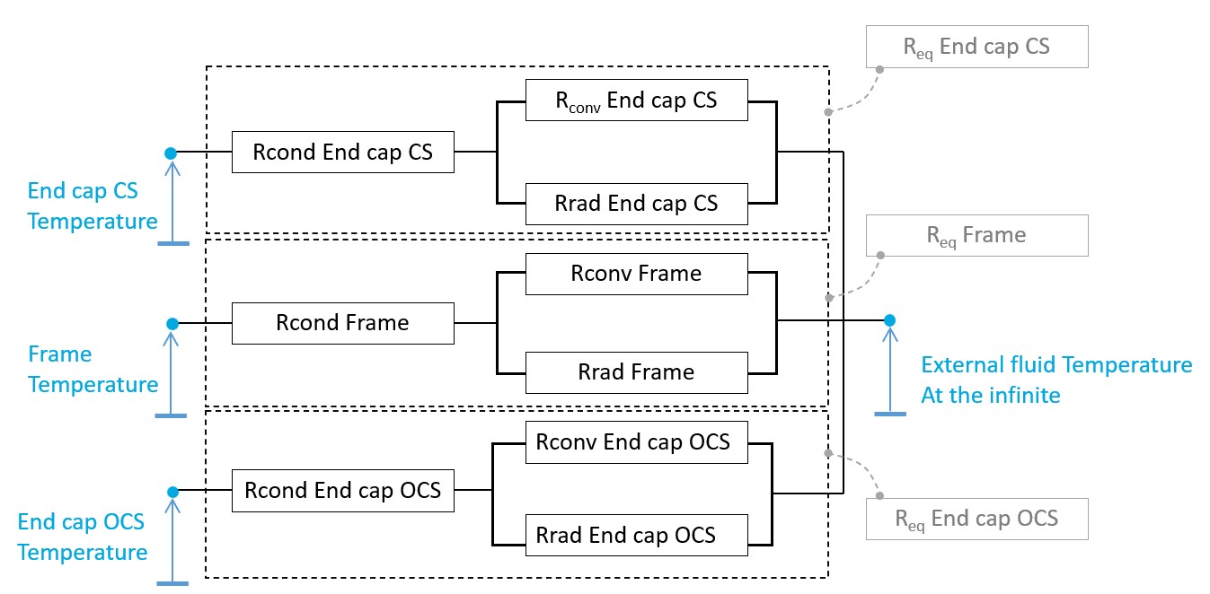
The thermal resistances defined above are integrated into the global thermal network. The part of this network corresponding to the end parts of the machine is described below.
Figure 2. Thermal resistance network including the interface gaps between the frame and the end caps 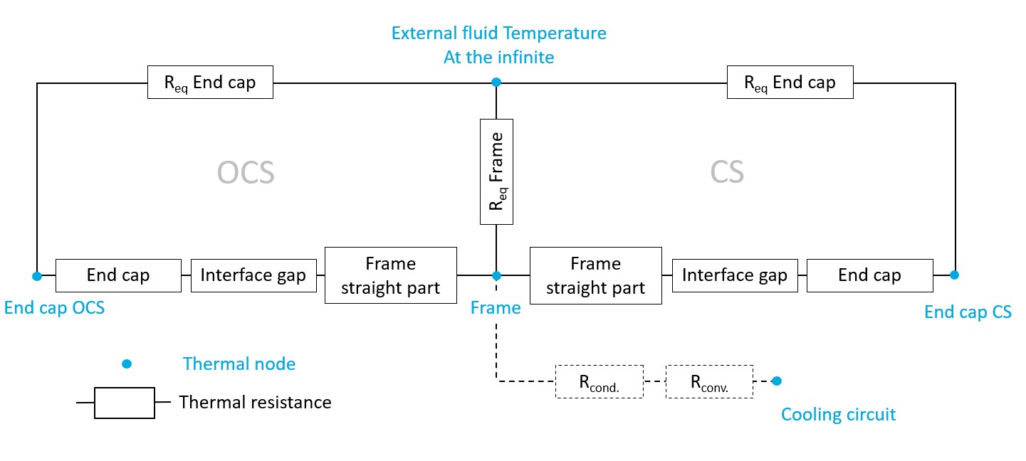
- Losses extracted to external fluid in temperature-speed area.
This graph shows the potential of the frame to extract losses in a temperature-speed area.
It shows, for a given frame temperature and a given rotation speed of the machine, how much losses are extracted from the frame to the external fluid, considering that the external fluid is at its reference temperature set by the user in the X-factor settings of the External cooling panel.
The map is plotted for a frame temperature going from the external fluid temperature to 150 K above this reference temperature.
-
Frame natural convection versus temperature (Resistance and convection coefficient)
These curves show the natural convection coefficients and resistances existing on each part composing the frame:- The straight part of the frame
- The Connection Side end cap
- The Opposite Connection Side end cap
These curves are plotted for a frame temperature going from the external fluid temperature set by the user in X-factor settings of the External cooling panel to 150 K above this reference temperature.
-
Frame forced convection versus speed (Resistance and convection coefficient)
These curves show the forced convection coefficients and resistances existing on each part composing the frame:- The straight part of the frame
- The Connection Side end cap
- The Opposite Connection Side end cap
The curves are plotted for a range of rotor speed going from zero to the maximum speed set by the user in the X-factor settings of the External cooling panel.
- Frame radiation versus temperatureThese curves show the radiation resistances existing on each part composing the frame:
- The straight part of the frame
- The Connection Side end cap
- The Opposite Connection Side end cap
These curves are plotted for a frame temperature going from the external fluid temperature set by the user in X-factor subset of External cooling panel, to 150 K above this reference temperature.
Cooling circuit
- Cooling circuit convection versus fluid velocity or debit (Resistance and
convection coefficient)
These curves show the convection coefficient and resistances existing in the cooling circuit versus the fluid velocity or debit.
The convection coefficient and resistance are plotted for speed or debit until the nominal value set by the user in the “Fluidic” settings of the External cooling panel.
These curves exist only when a cooling circuit is defined by the user in the Machine subset, Housing panel and Circuit setting.
- Cooling circuit Reynolds number versus fluid velocity or debit
This curve shows the Reynolds number existing in the cooling circuit versus the coolant speed or debit.
The Reynolds number is plotted for speed or debit until the nominal value set by the user in the “Fluidic” settings of the External cooling panel.
This curve exists only when a cooling circuit is defined by the user in the Machine subset, Housing panel and Circuit setting.
- Cooling circuit regular pressure drop versus fluid velocity or
debit
This curve shows the regular pressure loss existing along the cooling circuit versus the coolant speed or debit.
The computation of the regular pressure loss is based on the roughness set by the user and the Reynolds number in the pipe.
The regular pressure loss is plotted for speed or debit until the nominal value set by the user in the “Fluidic” settings of the External cooling panel.
This curve exists only when a cooling circuit is defined by the user in the Machine subset, Housing panel and Circuit setting.Note: only the regular component of the pressure loss is displayed. The singular pressure losses due to bends, pumps, section increases, or decreases are not represented.