Fluidic
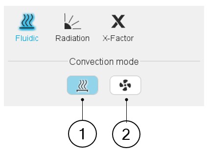
Convection mode
- On the external surfaces of the frame and of the end caps
- In the cooling circuit, when a cooling circuit is defined by the user (Machine subset, Housing panel, Circuit setting).
Two choices are available to define the convection occurring on the external surface of the frame and of the end caps: Natural or Forced.
By default, Convection mode is set to “Natural”.
 |
|
|---|---|
| 1 | Natural convection |
| 2 | Forced convection |
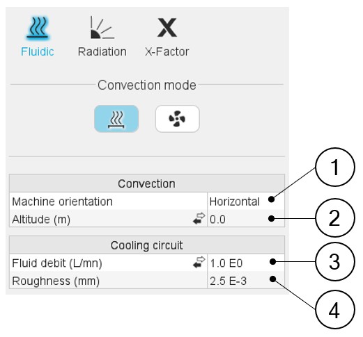
Natural convection
Natural convection is caused by the difference of fluid temperatures (giving a difference of fluid density). For instance, for a totally enclosed machine, cooled by natural convection in air, the frame will be hotter than the air close to it. This will warm the air surrounding the frame, feeding a natural « convective pump » due to the difference of air densities close and far from the frame (the hotter air having a lower density).
 |
|
|---|---|
| 1 | Machine orientation. The resulting orientation can be seen in the axial view of the machine. Machine orientation has an impact on the natural convection occurring on the external surface of the frame and the end caps. |
| 2 | Altitude or Pressure (depending on the input mode selected by the
user). The pressure has an impact on the gas properties, changing the convection (natural and forced) occurring inside and outside the frame. This pressure can be set directly as a pressure or as an altitude of use of the machine, depending on the user’s choice. When selecting the altitude, an
internal model computes the equivalent atmospheric pressure to
consider for the convection computations. Note:
|
| 3 | Fluid debit or Fluid velocity (depending on the input mode
selected by the user). This input exists only when a cooling circuit has been defined by the user in the Machine subset, Housing panel, Circuit setting. It corresponds to the fluid flow debit or velocity existing in the cooling circuit. This input will be considered for every thermal computation, including the tests (and not only for the model evaluation in the external cooling design environment). |
| 4 | The roughness of the cooling circuit pipe is only considered to compute the regular pressure losses in the cooling circuit and does not affect the computation of the temperatures. |
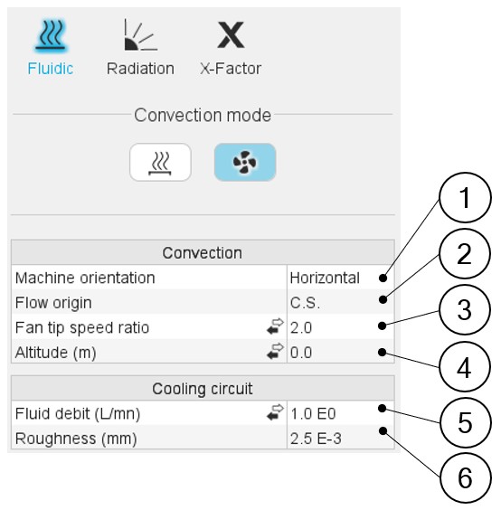
Forced convection
This convection mode allows to consider forced convection. When selecting this mode, the effect of the forced fluid flow around the machine is detailed separately from the natural convection in the results.
 |
|
|---|---|
| 1 | Machine orientation. The resulting orientation can be seen in the axial view of the machine. The machine orientation has an impact only on the natural convection occurring on the external surface of the frame and of the end caps. |
| 2 | Flow origin. This describes the origin of the fluid flow cooling
the external surfaces of the frame and the end caps. The flow can
come from the Connection Side or from the Opposite Connection
Side. Arrows are displayed in the axial view of the machine to illustrate the user choice. 3 Fan tip speed ratio or Constant fluid speed or Forced convection coefficient. (depending on the input mode selected by the user). This input describes the forced convection phenomenon existing on the outer surfaces of the frame and of the end caps. Please refer to additional information below. |
| 3 | Fan tip speed ratio or Constant fluid speed or Forced convection
coefficient. (depending on the input mode selected by the
user). This input describes the forced convection phenomenon existing on the outer surfaces of the frame and of the end caps. Please refer to additional information below. |
| 4 | Altitude or Pressure (depending on the input mode selected by the
user). The pressure has an impact on the gas properties, changing the convection (natural and forced) occurring in and out of the frame. This pressure can be set directly as a pressure, or as an altitude of use of the machine, depending on the user’s choice. When selecting the altitude, an
internal model computes the equivalent atmospheric pressure to
consider for the convection computations. Note:
|
| 5 | Fluid debit or Fluid velocity (depending on the input mode
selected by the user). This input exists only when a cooling circuit has been defined by the user in the Machine subset, Housing panel, Circuit setting. It corresponds to the fluid flow debit or velocity existing in the cooling circuit. This input will be considered for every thermal computation, including the tests (and not only for the model evaluation in the external cooling design environment). |
| 6 | Roughness: The roughness of the cooling circuit pipe is only considered to compute the regular pressure losses in the cooling circuit and does not affect the computation of the temperatures. |
 |
|
|---|---|
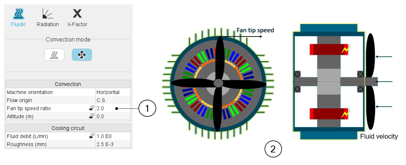
| 1 | Fan tip speed ratio or Constant fluid speed or Forced convection
coefficient. (depending on the input mode selected by the
user). This input describes the forced convection phenomenon existing on the outer surfaces of the frame and of the end caps. The fan tip speed ratio describes the ratio between the fluid velocity and the tip speed of the rotor. It models the behavior of a shaft mounted fan whose rotation depends on the speed of the rotor. Then, when using this input, the external fluid velocity along the frame will be proportional to the rotation speed of the rotor. |
| 2 | The user set the ratio between the fan blade tip speed (the tip
of the blades being considered at the frame’s external radius,
without considering the possible fins and the velocity of the fluid
projected by the fan). The default value is 2. This corresponds to average fans, where the tip speed of the fan blade is two times higher than the average speed of the fluid projected by the fan. The lower this ratio is, more efficient the cooling will be (because with a lower ratio, the coolant velocity will be higher at a given rotation speed of the rotor). Constant fluid speed input can be used to model a fixed coolant velocity, whatever the rotor speed is. It allows modeling an external cooling system blowing air on the machine without dependency on the machine. Forced convection coefficient input allows experts to directly establish in the model a forced convection coefficient. |