Expert mode - Table
1. Expert mode dialog box
 |
|
| Building the winding architecture – Filling of the connection table | |
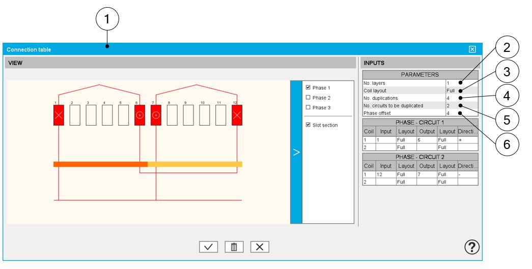
| 1 | Dialog box to define a coil with Expert mode |
| 2 |
Selection of the number of layers. The solutions depend on the number of slots and the number of poles and the number of phases. Example: With 12 slots and 10 poles and 3 phases, only one solution is proposed: 1 layer. The three possible cases are illustrated in the Easy mode section. |
| 3 |
Definition of the coil layout i.e. how the coil sections are distributed into the slot. The three possible choices are:
The solutions depend on the number of slots and the number of poles. Example 1: With 12 slots and 10 poles and 3 phases, two solutions are proposed: superimposed or adjacent. Note: In such case, only toothed winding is relevant.
This corresponds to an adjacent coil layout.
Example 2: With 48 slots and 8 poles and 3 phases, one solution is imposed: Full. |
| 4 |
Definition of the number of duplications. This number is computed and proposed to the user. It depends on the number of slots and the number of poles. When the winding architecture to build is cut into several identical parts, the corresponding possible number of duplications are proposed (a short list). By selecting the number of duplications, the user must define only 1/n of the connection table. |
| 5 |
Number of circuits to be duplicated represent the number of elementary circuits to be defined inside each sector to be duplicated. In this example 2 circuits are defined in the represented sector. This is why, there are 2 connection tables to be filled in. One for each circuit: Phase 1 – Circuit 1 and Phase 1 – Circuit 2 |
| 6 | Phase offset – See illustration below. |
 |
|
| Building the winding architecture – Filling of the connection table | |
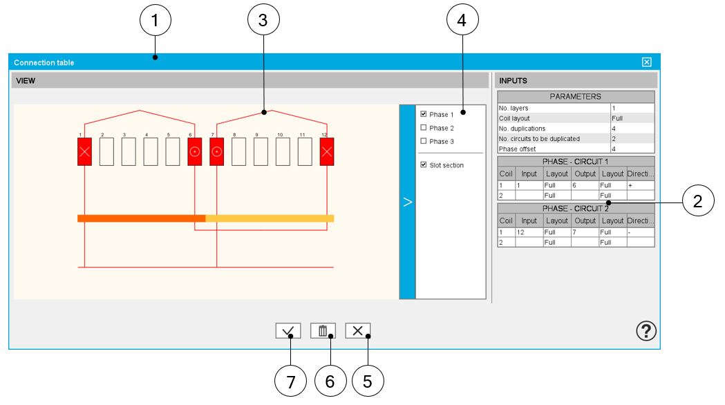
| 1 | Dialog box to define a coil with expert mode |
| 2 |
The connection table(s) must be filled in. 1 or 2 according to the number of circuits to be represented inside the considered elementary sector.
|
| 3 | Display of the 3-Phase winding |
| 4 | Make the phase visible or not |
| 5 | Button to cancel action and close the panel. |
| 6 | Button for erasing everything in the connection table (Erase connection table data). |
| 7 | Button to apply inputs and close the panel. |
2. Coil layout in slot
 |
|
| Building the winding architecture – Definition of coil layout | |
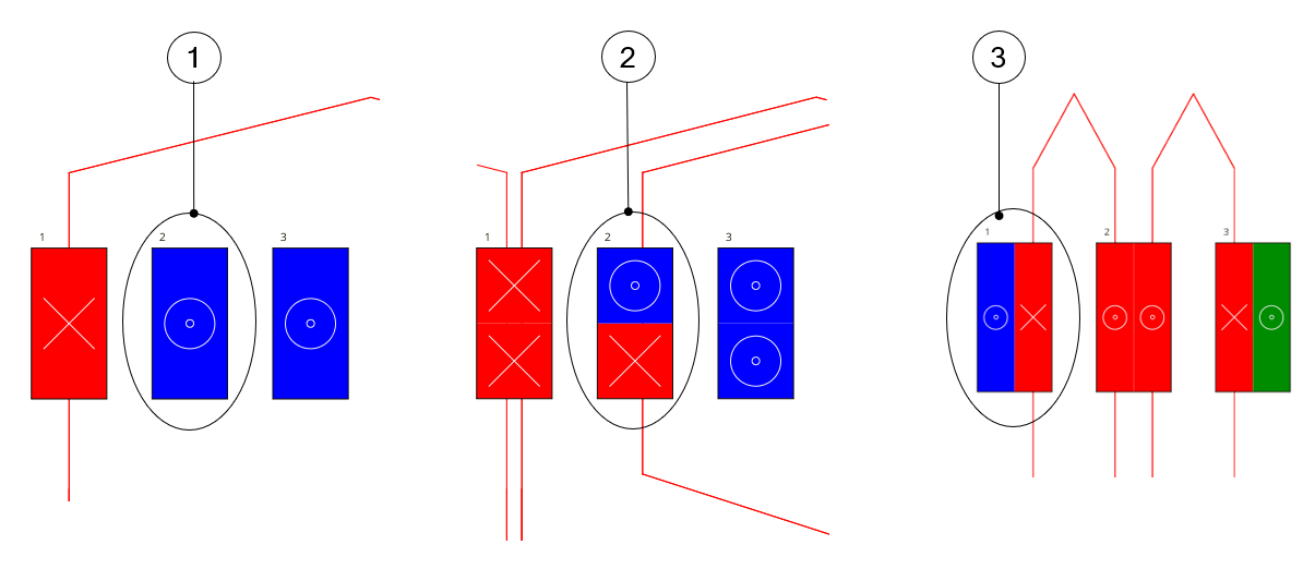
| 1 | Example where the coil layout is Full. |
| 2 | Example where the coil layout is Superimposed. |
| 3 | Example where the coil layout is Adjacent. |
3. Phase offset parameter
 |
|
| Building the winding architecture – Filling of the connection table – Phase offset | |
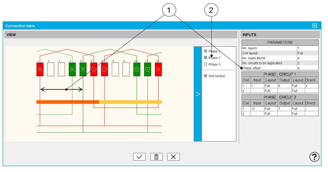
| 1 | Definition of the phase offset = number of slot pitch between each phase. |
| 2 | Make the phase visible or not. Note: All the
phases are identical. Phases 2 and 3 are identical to Phase 1 and is
displayed in the winding by considering the phase offset. |
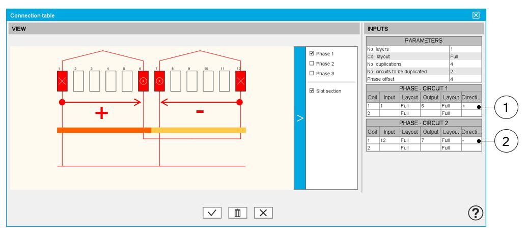
Winding direction for coils
 |
|
| Orient the coils when defining the phase circuits | |
| 1 | Definition of a positive orientation of coil i.e., in the clockwise direction from the connection size (=ascending order of slot numbers) |
| 2 | Definition of a negative orientation of coil i.e., in the counterclockwise direction from the connection size (=descending order of slot numbers) |
4. Additional information
The real distribution of the parallel paths in the winding is taken into account for performing the tests. It wasn’t the case informer versions. Hence, it wasn’t possible to know how the parallel paths are distributed and sometimes this led to a error. This issue has been fixed.
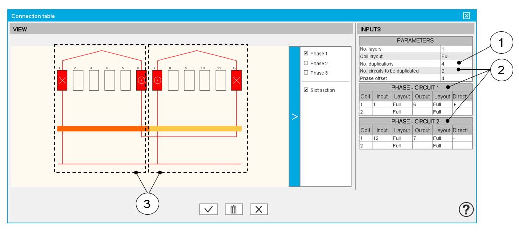
From now on, one need to know how the parallel paths were distributed. To do that, in the expert mode, to define the connection table, the user can define the number of circuits to be duplicated and for that, he must fill in a connection table for each elementary parallel path.
 |
|
| Dialog box for defining the connection table while using the expert mode | |
| 1 | Number of duplications. See the definition in table above. |
| 2 | Number of circuits to be duplicated. See the definition in table above. |
| 3 | Representation of the two circuits inside the considered sector. |
Then, the list of possible number of parallel paths « No. parallel paths » adapts itself in function to the number of duplications « No. duplications » and the number of circuits to be duplicated « No. circuits to be duplicated ».
Here is the resulting layout of the winding architecture below. There are always 4 possible parallel paths. These circuits can be well connected.
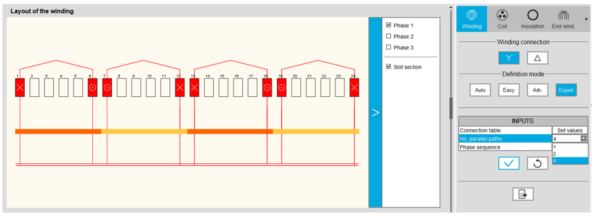 |
| Layout of the resulting winding architecture |
This modification is a problem for motors the number of parallel paths « No. parallel paths » of which is greater to the number of duplications « No. duplications »
In that case, one has decided to modify the value of the « No. parallel paths » to make it take the value of the « No. duplications ».