The network planning of a local area network in an urban scenario is investigated.
The intelligent ray tracing model (IRT) method is used.
Sites and Antennas
Five omnidirectional antennas are placed at different sites. They use three different
carrier frequencies around 2.4 GHz. All the antennas are placed at a height of 15 m.
Tip: Click Project > Edit Project Parameter and click the Sites tab to view the sites
and antennas.
Open the Edit Project Parameter dialog and click the
Sites tab for details.
Air Interface
The wireless local area network (WLAN) air interface is defined by the 802.11b
wireless standard (.wst) file. CDMA/WCDMA/HSPA (code division
multiple access) is selected for multiple access. In this model, time division
duplex (TDD) is used for duplex separation, which is switching between uplink and
downlink.
Tip: Click Project > Edit Project Parameter and click the Air Interface tab to view
the carriers and transmission modes.
Computational Method
The computational; method, 3D: Rigorous IRT (Intelligent Ray
Tracing), is selected. This prediction method results in high
accuracy, and due to the preprocessing of the database, requires a short computation
time.
Tip: Click Project > Edit Project Parameter and click the Computation tab to change
the model.
Results
Propagation results show at every location the power received from each transmitting
antenna.
The type of network simulation used is a static simulation (homogeneous traffic per
cell). The network simulation calculates the maximum received power,
Eb/N0 (max) and maximum achievable
Ec/(N0+I0) for all modulation and coding
schemes used in this model for both downlink and uplink.
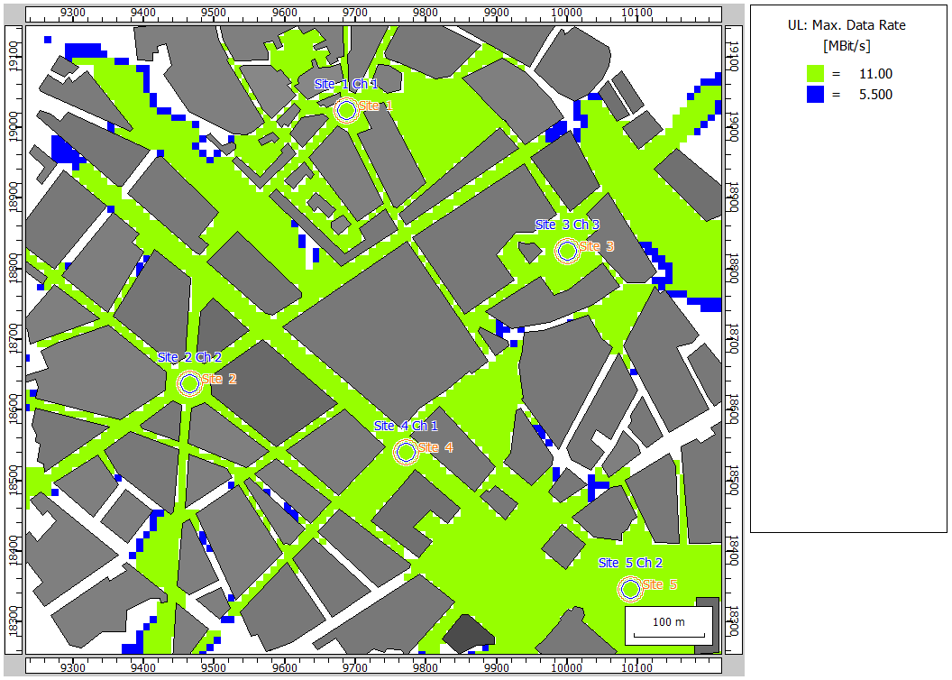
Figure 1 shows the maximum
achievable data rate for communication with this wireless standard in this
model.