Indoor Communication, 2.5G

The network planning of an indoor scenario is investigated. The geometry is a large convention center.
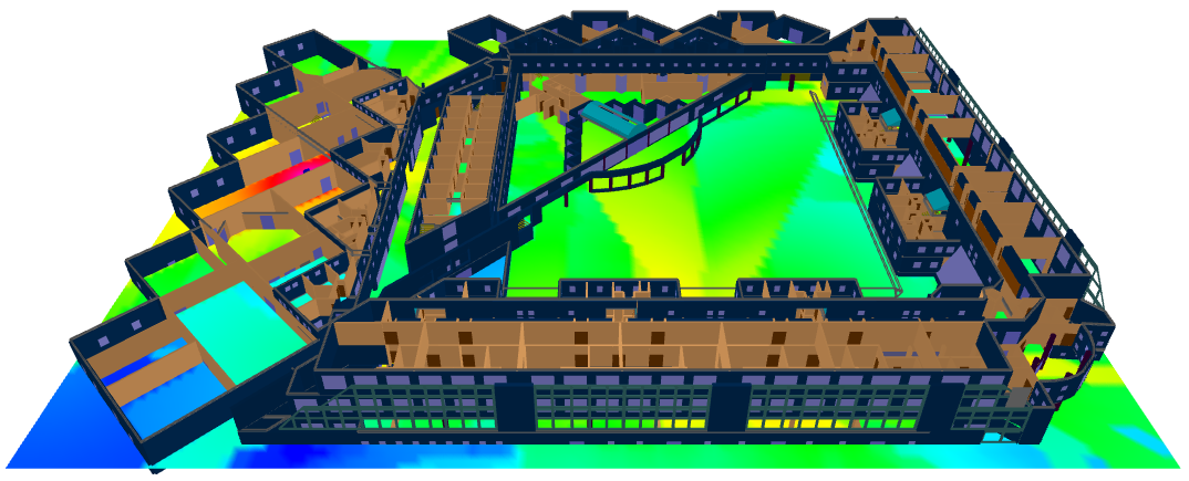


Figure 1. A 3D view of the large convention center.

Sites and Antennas

There are three antenna sites in different locations in the convention center. The antennas used are vertically polarized antennas with imported antenna patterns.

Air Interface

The air interface is defined by a GSM wireless standard (.wst) file. TDMA (time-division multiple access) was selected for multiple access. The number of time slots on a carrier is 8. Along with this, all available carriers and transmission modes are listed here.
Tip: Click Project > Edit Project Parameter and click the Air Interface tab.

Computational Method
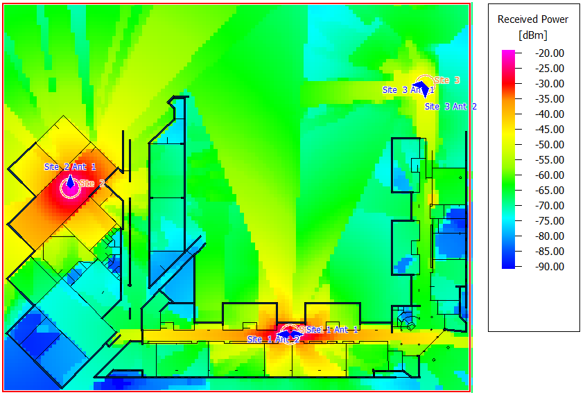
As the model is a large multi-floor building, the computation method used for such models is the dominant path model (DPM). DPM focuses on the most relevant path, which leads to shorter computation times than standard ray tracing model (SRT).
Tip: Click Project > Edit Project Parameter and click the Computation tab to change the model.

Results

Propagation results show, at every location, the power, and field strength received from each transmitting antenna individually.

Network planning results show, among other results, the power at every location received from the antenna that serves it. Figure 2 shows the received power at a height of 1.5 m. The power received from site 3 is lower because site 3 is on a higher floor.


Figure 2. The received power results for network planning.

The type of network simulation used is a static simulation (homogeneous traffic per cell). The network simulation calculated minimum transmission power, SNIR(max), reception probability (including fast fading) for both downlink and uplink.

Site 1 and site 3 have two antennas each, and site 2 has only one antenna. The orientations of the antennas are selected to achieve the best indoor propagation. Indeed, high data rates and high receive probability are achieved almost everywhere