Indoor UWB Using IRT
Perform network analysis for ultra-wide band (UWB) frequencies in an indoor scenario.
Air Interface
A total of 36 carriers from 3.1 GHz to 10.1 GHz were defined on the Air Interface tab. The properties of the mobile station (the receiving antenna anywhere in the computational domain) are also defined here. The receiver needs a power level of at least -90 dBm.
Sites and Antennas
A single omnidirectional antenna is located in an indoor environment. The purpose of the simulation is to determine the coverage for a wide range of frequencies. Under the properties of the antenna, instead of assigning one carrier to the transmitter, the UWB air interface has automatically assigned all carriers.
Computational Method
The database was preprocessed in WallMan, and the intelligent ray tracing model (IRT) is used.
Results
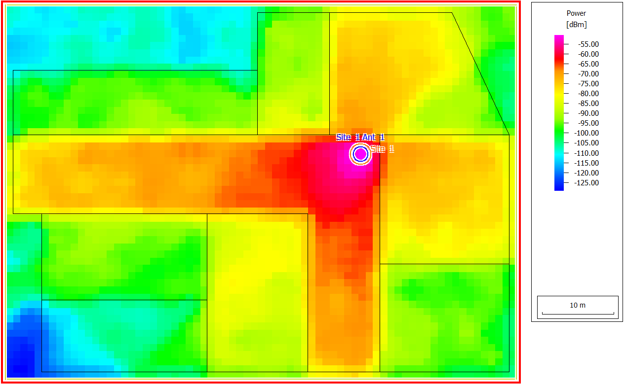
Received power can be displayed for every carrier. In Figure 1, the power for carrier 8 is displayed.
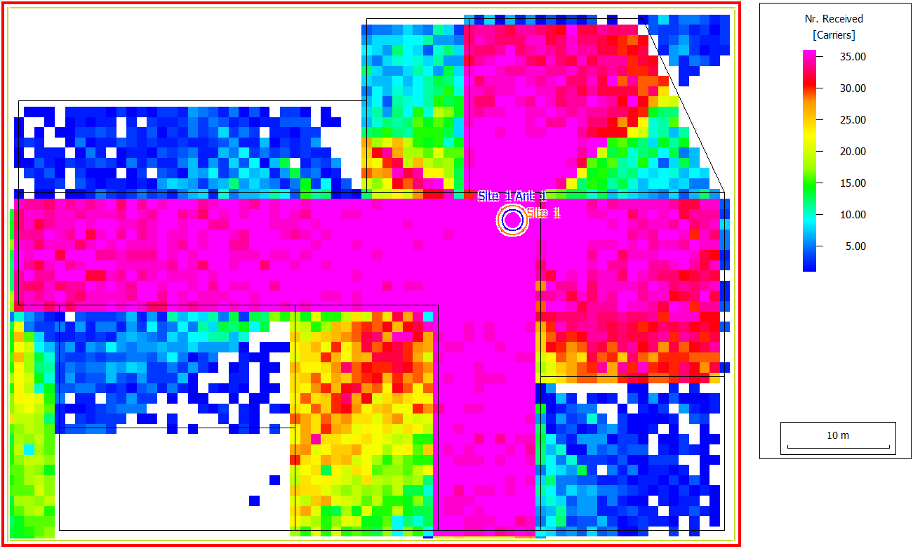
When not all carriers are received, it is likely that the higher frequencies are missing as they suffer higher losses during transmission through walls and during diffraction at corners.