LoRaWAN and IoT
Perform network planning for the internet of things (IoT) in an urban scenario.
Sites and Antennas
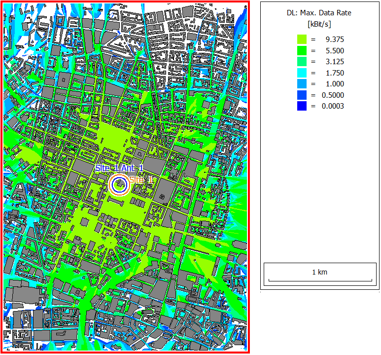
A single monopole antenna is located on the roof of a building in an urban area. This antenna represents the transmitter antenna of a gateway in an IoT network. The goal is to determine whether the gateway can communicate with all the wireless sensors in the area and to determine the data rates that can be achieved.
Air Interface
| Bandwidth (kHz) | Spreading Factor | Data Rate (bps) | Receive Sensitivity (dBm) |
|---|---|---|---|
| 125 | 12 | 300 | -136 |
| 125 | 11 | 500 | -133 |
| 125 | 10 | 1000 | -132 |
| 125 | 9 | 1750 | -129 |
| 125 | 8 | 3125 | -126 |
| 125 | 7 | 5500 | -123 |
| 125 | 6 | 9375 | -118 |
Computational Method
The computational method is the dominant path model (DPM). This method focuses on the most relevant path, which leads to shorter computation times compared to ray tracing.
Results
The propagation analysis determines the power received by a hypothetical isotropic antenna at every location. The network planning compares those results with the minimum required received power for any transmission mode, taking into account the receiver settings for antenna gain and general device losses. For every transmission mode, the minimum SNIR is also considered, taking into account the thermal noise and the receiver’s noise figure.