The network planning of a local area network in an urban scenario is investigated.
The dominant path model (DPM) is used.
Sites and Antennas
There are seven antennas located at different sites. All the antennas are mounted at
a height of 15 meters. Some antennas consist of sector antennas and some of
omnidirectional antennas. They use three different carrier frequencies around 2.4
GHz.
Tip: Click Project > Edit Project Parameter and click the Sites tab to view the sites
and antennas.
Air Interface
The wireless local area network (WLAN) air interface is defined by an 802.11g
wireless standard (.wst) file. OFDM/SOFDMA (orthogonal
frequency-division multiplexing) is selected for multiple access. It uses time
division duplex (TDD) for switching between uplink and downlink. In TDD, only
downlink carriers are defined, since uplink and downlink are separated in time. In
this model, the adaptive switching method is used depending on the traffic load.
Tip: Click Project > Edit Project Parameter and click the Air Interface tab to view
the carriers and transmission modes.
Computational Method
The computational method used for this model is the DPM. The DPM focuses on the most relevant path, which
leads to shorter computation times compared to ray tracing.
Tip: Click Project > Edit Project Parameter and click the Computation tab to change
the model.
Results
Propagation results show at every location the power received from each transmitting
antenna.
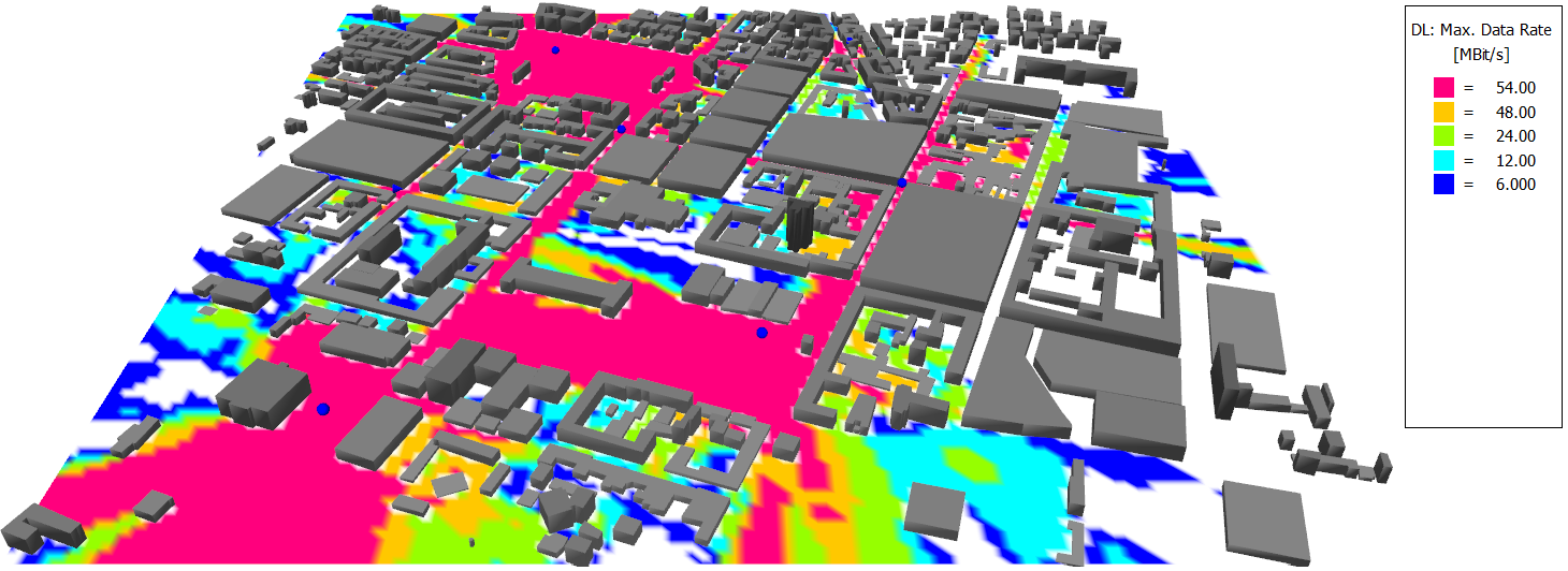
The network-planning simulation computes, among other things, the
signal-to-noise-and-interference ratio (SNIR), the maximum received power, and the
achievable data rate with this air interface. The data rates are shown in Figure 1.Figure 1. Download data rates for the urban network planning.