1 Click SPH Creation
![]()
Description
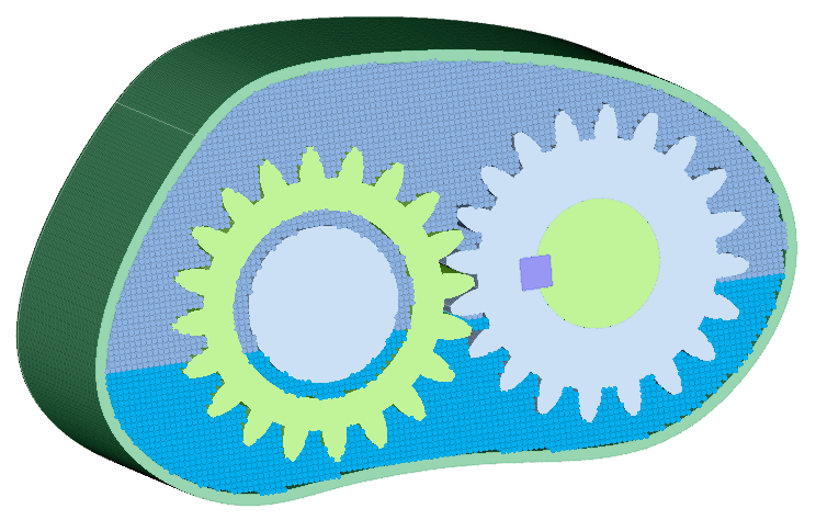
This option is used to generate a uniformly distributed particle for the nanoFluidX (nFX) solver. The particles form a grid in the global XYZ axis with one point at the origin. The output from this operation is a point mesh (point body). The SPH particles are the nodes.The input geometry can be CAD or FE models.
A model typically has solids that are stationary (outer container for example), solids that move (gears, shafts, etc.) and sometimes solids that represents the liquid and gas (fluids) inside the container. The stationary part is modelled as is or, to improve solver performance, the wetted surface is identified and a thick region is created. The moving parts are modelled as hollow solids. If the fluid regions are represented as solids then they are meshed as is. In the absence of solids for the fluid regions, the fluid region is defined by a node contained in the fluid region. The fluid - fluid interface (mostly liquid - gas interface) is defined by the plane and the software automatically creates particles for both the fluid regions (liquid and gas).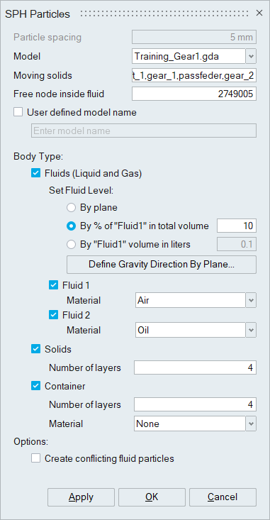
Particle spacing
Particle spacing is the distance between adjacent particles in the global coordinate axis. The particles are uniformly distributed along the global XYZ axis. This spacing is used when generating the particles for stationary parts, moving parts and the fluid regions.
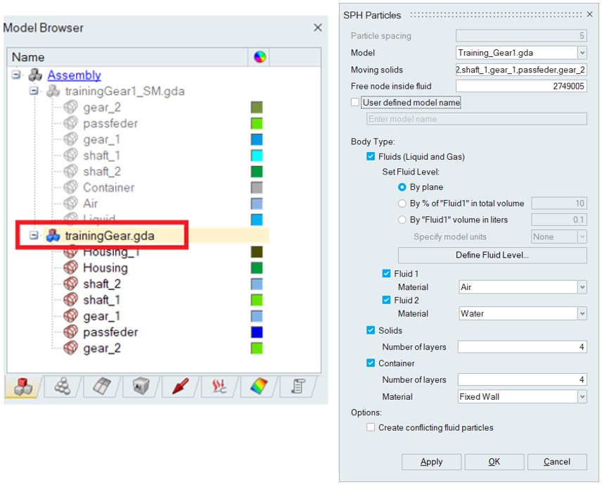
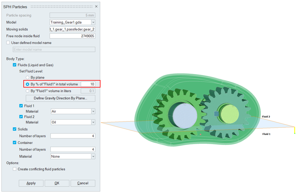
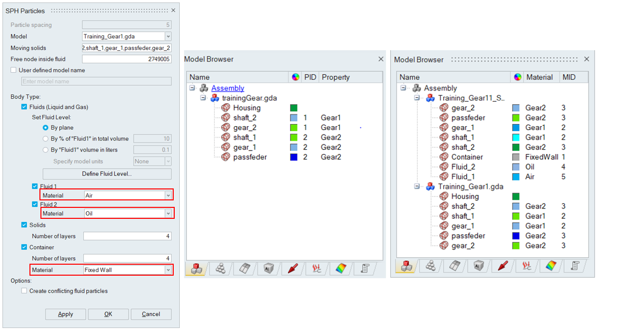
Body Type: Fluids (Liquid and Gas)
This option helps to define and create the fluid (liquid and gas) regions inside the container. This is useful when the CAD or FE model does not have a separate body for the fluids (liquid and gas).The model for which fluid particles has to be created must be selected from the Model drop down. In this selected model only necessary bodies that are required for generating fluid domain, solids and container must be present. If any mass flow bodies are present, they have to be moved to another model. In addition, a free node inside the fluid is to be selected. Particles for either Fluid 1 or Fluid 2, or both can be generated as required.
The fluids can be generated using
- By plane (or)
- By percentage of "Fluid1" in total volume (or)
- By "Fluid1" volume in litres.
"Define Fluid Level" helps to define a plane that separates the fluids (liquid and gas) and its normal points to the Fluid 1 region.
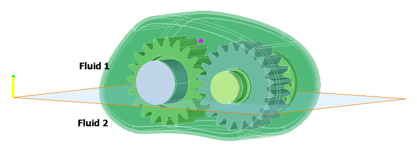
The resultant liquid and the gas regions are shown below.
It helps to generate the fluids based on the specified percentage of Fluid 1 volume.
The reference plane and the Fluid 1 region/gravity direction is defined using "Define Gravity Direction By Plane" option.
In above use case, user specified 10% of "Fluid 1" volume and its corresponding
fluid regions are generated as shown below. 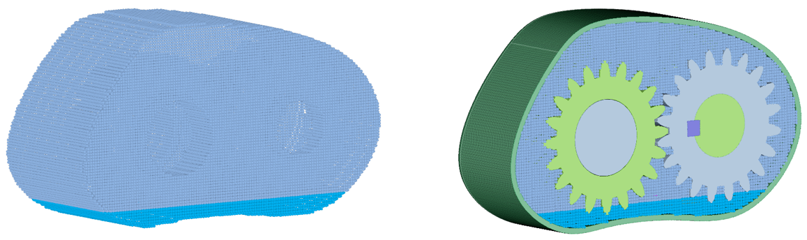
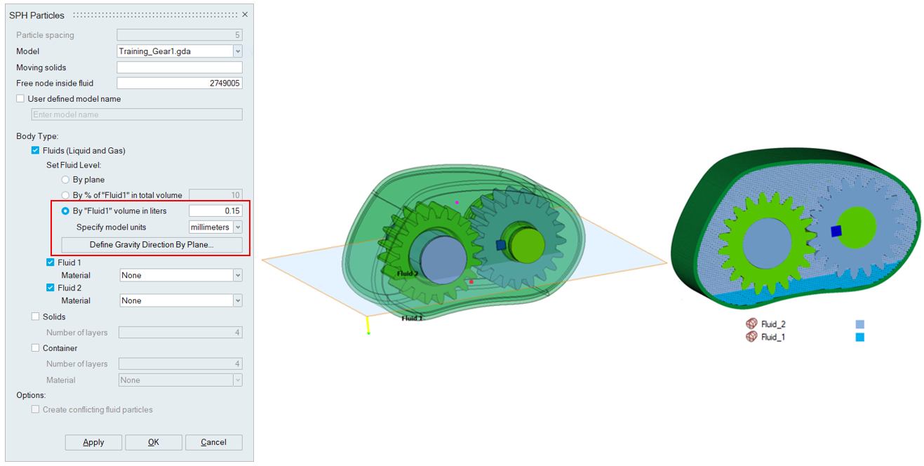
It helps to generate the fluids based on the specified Fluid 1 volume in litres.
The reference plane and the Fluid 1 region/gravity direction is defined using "Define Gravity Direction By Plane" option.
If unit system is disabled, "Specify model units" is used to specify the unit of the selected model.
Required number of Fluid 1 particles is calculated using following formula.

Here,
Specified volume in litres is converted to volume in cubic units of the selected model based on following conversion
- 1 Litre = 1000000 cubic millimetre
- 1 Litre = 1/1000 cubic meter
- 1 Litre = 61.024 cubic inches
Volume of each particle = (particle spacing)^3. Volume of cube is considered instead of volume of sphere to avoid volume errors.
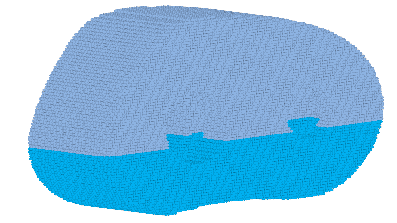
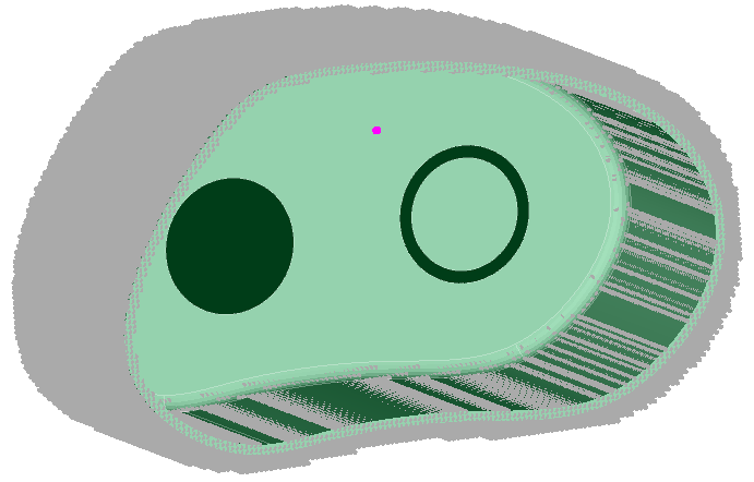
Total fluid capacity of below mentioned gear housing model is 1 litre. 0.15 litres of Fluid 1 particles is obtained as shown below.
Modifying the fluids is available under nFx Tools | Particle Creation | Create/Modify Particles .
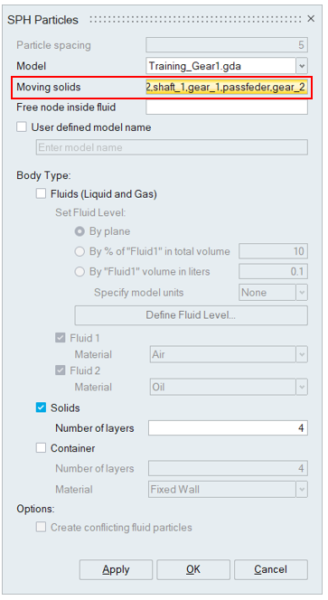
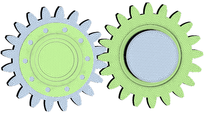
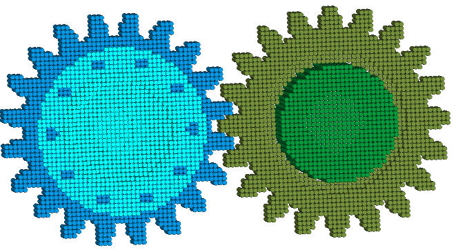
Body Type: Solid
This option helps to create particles for the bodies selected as Moving solids, like gears, shafts, or casings which are solids. Particles will be created inside the solid region. To reduce model size, users can model the solids as a thick solid (hollow inside) without impacting the results. To facilitate this, users can specify a finite number of layers of particles needed from the solid surface. If the number of layers is specified as 0, all the particles inside the solids will be created. This can also be used for liquid or gas regions modelled as solids in the geometry.
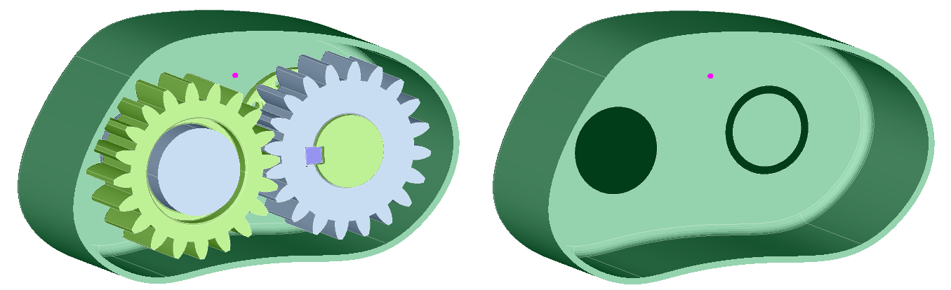
Body Type: Container
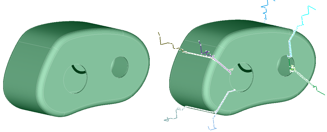
Sometimes the outer casing can have features like bolt holes, ribs, etc. which do not impact the solution. It is more efficient to generate the model without these features. This is achieved by identifying solids that define the container (should not include the moving parts and should be closed and should not have gaps bigger than the particle distance) and a point inside the container where the fluids are present. The mesher will automatically identify the wetted surface (surface that is touched by the fluids) and create several layers of particles away from the wetted surface.In the below model, the moving solids (gears/shaft) are modelled as solids. So, while creating particles for container, the Moving solids should be ignored. Hence the bodies that would be considered for creating Container is bodies from the Model minus Moving solids.
Automatic leak detection
When generating particle mesh for Liquid and Gas and for Container, if any leaks are present, the leak paths will be displayed.
Automatic Materials and Motions transfer
When generating particle mesh for Solids, if Materials and Motions are defined for the input bodies, the output particle mesh inherits the same materials and motions.
For Fluid 1, Fluid 2 and Container, the user can select the Material to be assigned automatically after generating the particle mesh for the components.
- When an active SPH Flow Solution exists, the output particle bodies would be automatically added to the Solution Mesh bodies. If the Solution already contains the particle mesh for an input body, the particle mesh in the Solution would be replaced by the newly created particle body.
- Duplicate particles are automatically identified and moving solid particles are retained with high priority then static solids and then fluids.
- The faces specified in the "Inlet | Custom | Select faces" and “Probes | Massflow probe | Custom surface” is ignored in particle creation.
- Three layers of missed out particles between fluids and solids interaction are
created for the following use cases
- On creating fluids, solids and all bodies are considered as moving solids
- On creating fluids, solids and container.